29
15.5 INSTALLATION AND REPLACEMENT OF FUSE-LINKS
A red indicator below the fuse symbol on the lower front panel
indicates that at least one fuse-link has blown. Fuse links are
replaced as shown in the sequence of illustrations. Switch-
fuse configurations are supplied without fuse-links installed.
When installing fuse-links for the first time, follow the
sequence of illustrations 2-9.
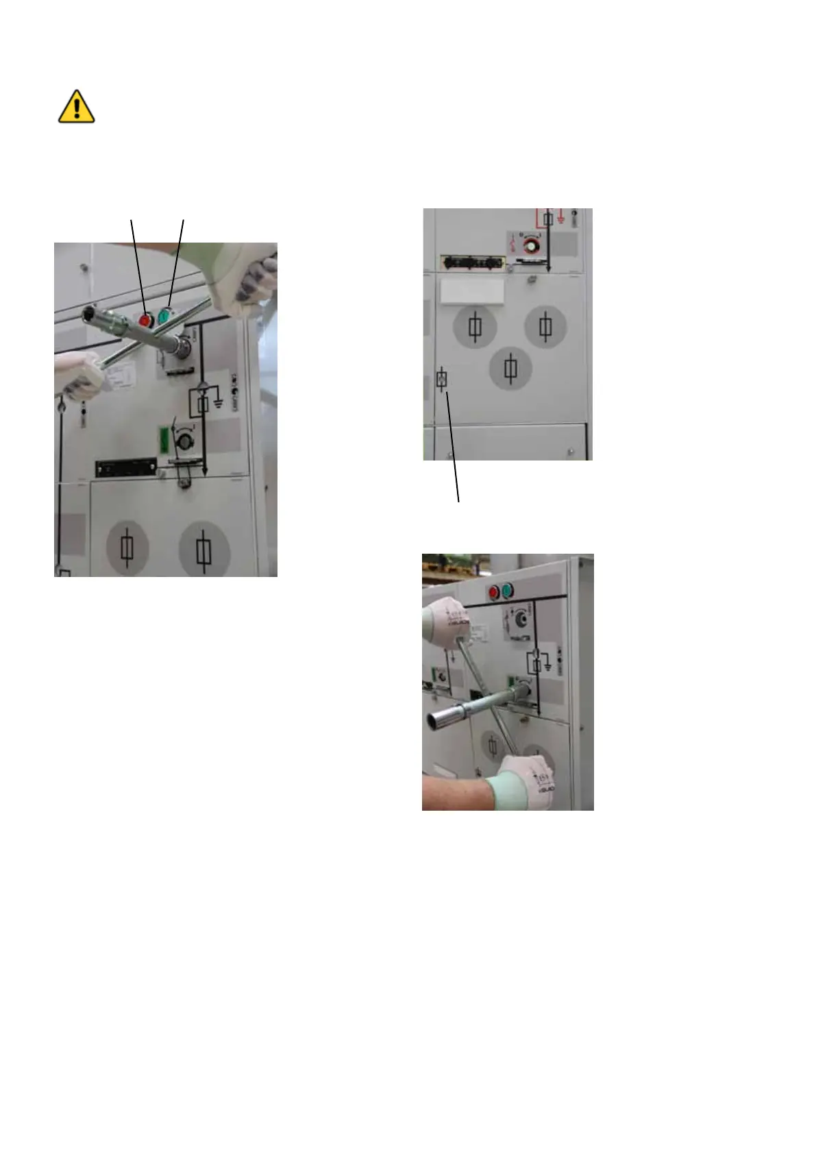
1. Blown fuse indicator.
2. Close earthing switch by turning operating handle
clockwise.
15.4 OPERATION OF FUSE-SWITCH DISCONNECTOR
Switch-fuse disconnector:
Charging springs: Turn the operating handle clockwise to
charge the closing and the opening spring.
Close: Push the green button (A)
Open: Push the red button.(B)
The circuit-breaker can be tripped by the protection relay,
while in switch-fuse configurations the fuse switch disconnec-
tor can be triggered by the fuse striker pin if an over-current,
a short-circuit or an earth-fault occurs.
WARNING
For correct function of F-module, it is required
to use fuses suitable for rating of protected
distribution transformer, see fuse selection
table on following pages. Use of improper
fuse can void the warranty.
B A