Section 4 Commissioning SAM600
4.1 Safety instructions
GUID-B026E4F3-1373-4144-BA89-F2B91094CE9A v1
Safety instructions must be followed as described in this operation manual and as described
in document 1KHL511872-UEN.
4.2 Unpacking
GUID-034AEFE4-380B-4E53-9B66-9A847C4C9BE4 v1
Upon receiving of the SAM600 modules check for any physical damage sustained during the
transport.
4.3 Mounting and earthing connection
GUID-D12420A7-9169-45CE-940C-2D8C8F607BBF v1
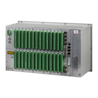
SAM600 modules are DIN-rail mounted and can be installed horizontally or vertically in a rack
or marshalling kiosk. Preferred mounting position is horizontal mounting.
The minimum spacing between SAM600 modules, and between SAM600 modules and cable
ducts as described in Section 7.1 must be observed.
The DIN rails onto which SAM600 modules are mounted must be properly connected to the
station earthing system. Use a conductor with a core cross section area of at least 4mm
2
(AWG12).
Each SAM600-CT and SAM600-VT module must be connected to protective ground in the
cubicle using a ground strap with the protective earthing screw (
Section 1.1).
4.4 Electrical wiring
GUID-9EE02EE4-1D18-4C78-9722-8C2D1C66E71F v1
Connecting the power supply
SAM600 modules are powered with 24V DC voltage. Use only approved DC/DC converters or
power supplies. Approved power supplies are listed in SAM600 accessory list (1MRK 511 436-
UEN).
The wiring from the cubicle terminal block (station battery) to the DC/DC converter must be
made in accordance with established standards for this type of equipment. Wiring from the
DC/DC converter to the SAM600 module uses a 3-pin connector.
Power supply connectors
Each SAM600 module has two power supply connectors (X1 and X2). This allows to connect the
SAM600 modules to individual power supply units. The two connections X1 and X2 are module
internally decoupled to support power supply redundancy.
The connectors accept conductors with a cross section area of 0.2-2.5 mm
2
(AWG 24-14,
Section 7.2.2). The conductors can be of rigid type (solid, stranded) or of flexible type. The
fastening screw shall be tightened with a torque of 0.4 Nm.
The wires shall be connected to the connector before it is plugged into the SAM600 module,
where the connector is then securely tightened with the two screws on each side of the
connector.
1MRK 511 434-UEN B Section 4
Commissioning SAM600
SAM600 Process Bus I/O System 29
Operation Manual
© Copyright 2017 ABB. All rights reserved