LED status indication D2/D9
Status indications D2.1-D2.4 NA For more details refer to
Section 7.2.3
Status indications D9.1-D9.4 NA For more details refer to
Section 7.2.3
7.2.3 LED indications for all SAM600 modules
GUID-CA1D6DAE-130B-45EE-A07F-6CAA2FBB492A v1
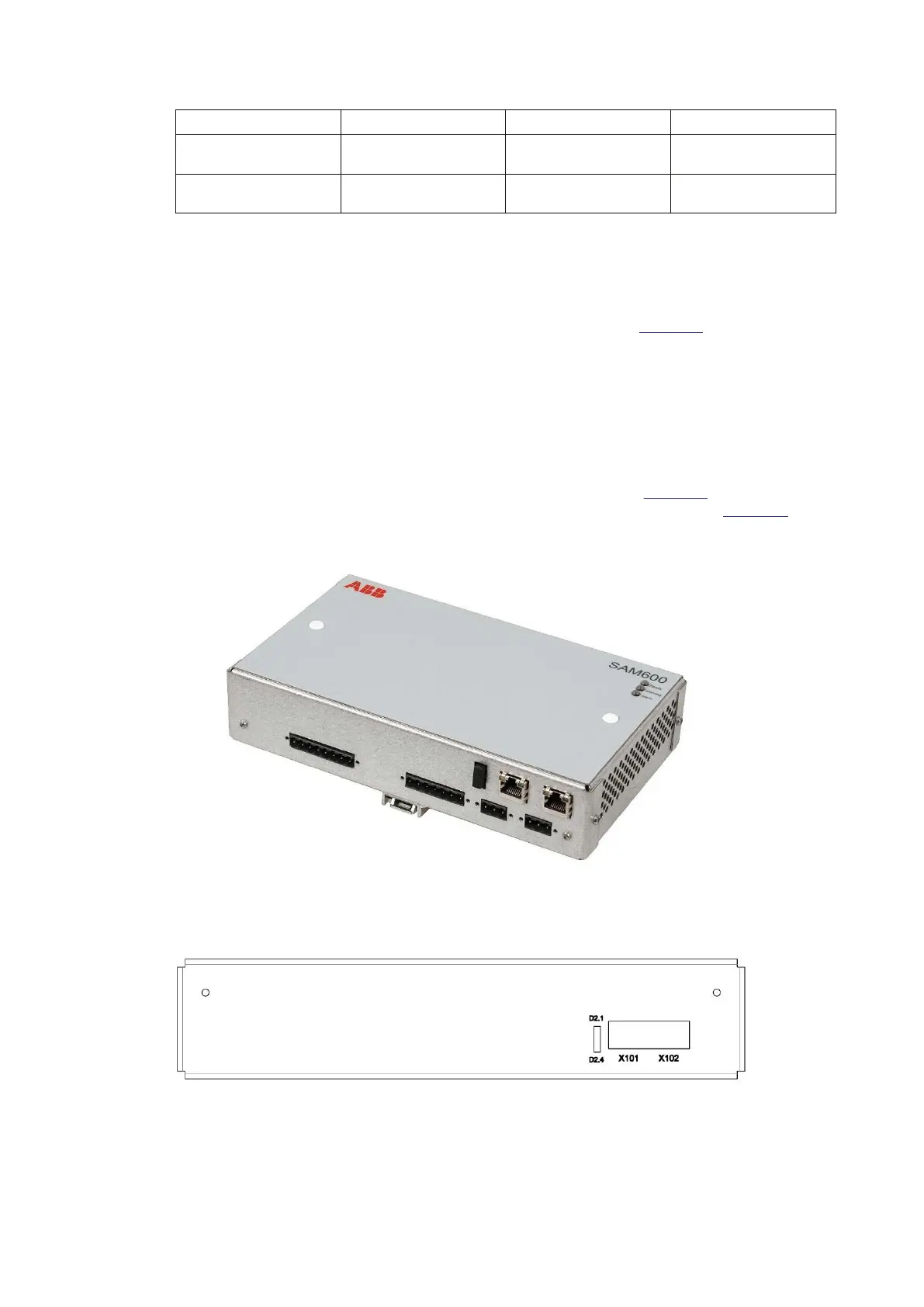
The SAM600 modules contain several LEDs to indicate the current operation states. The main
SAM600 module indication LEDs are located on the front side (see
Figure 22). These 3 LEDs are
common for all the three SAM600 module. Enumerated from top to bottom these LEDs are
indicating:
• Ready (green)
• Warning (yellow)
• Alarm (red)
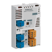
There are 4/8 more LEDs on the sides that indicate the network activity and link state of the
optical transceivers. For SAM600-CT and SAM600-VT modules (see
Figure 23), there are 4 LEDs
for the optical transceivers link state and there are 8 LEDs for SAM600-TS (see Figure 24).
IEC18000512 V1 EN-US
Figure 22: Top side view with LEDs
IEC18000532 V1 EN-US
Figure 23: CT/VT side of the optical transceivers with the LEDs D2.1 to D2.4
Section 7 1MRK 511 434-UEN B
Technical Data
46 SAM600 Process Bus I/O System
Operation Manual
© Copyright 2017 ABB. All rights reserved