20 TTH300 HEAD-MOUNT TEMPERATURE TRANSMITTER | OI/TTH300-EN REV. E
8 Electrical connections
Safety instructions
DANGER
Improper installation and commissioning of the device
carries a risk of explosion.
For use in potentially explosive atmospheres, observe the
information in Use in potentially explosive atmospheres in
accordance with ATEX and IECEx on page 6 and Use in
potentially explosive atmospheres in accordance with FM
and CSA on page 12!
Observe the following instructions:
• The electrical connection may only be established by
authorized specialist personnel and in accordance with
the connection diagrams.
• The relevant regulations must be observed during electric
installation.
• The electrical connection information in the instruction
must be observed; otherwise, the electric IP rating may
be adversely affected.
• Safe isolation of electric circuits which are dangerous if
touched is ensured only if the connected devices satisfy
the requirements of DIN EN 61140 (VDE 0140 Part 1)
(basic requirements for safe isolation).
• To ensure safe isolation, install connection leads separate
from electric circuits which are dangerous if touched, or
implement additional insulation measures.
• Connections must only be established in a dead-voltage
state!
• The transmitter has no switch-off elements. Therefore,
overcurrent protective devices, lightning protection, or
voltage disconnection options must be provided with the
installation.
• The power supply and signal are routed in the same
conductor and should be implemented as a SELV or PELV
circuit in accordance with the relevant standard
(standard version). For the explosion-proof design, the
guidelines in accordance with the Ex standard must be
adhered to.
• You need to check that the available power supply
corresponds to the information on the name plate.
Note
The signal cable wires must be provided with wire end sleeves.
The slotted screws of the connection terminals are tightened
with a size 1 screwdriver (3.5 or 4 mm).
Protection of the transmitter from damage
caused by highly energetic electric
interferences
The transmitter has no switch-off elements. Therefore,
overcurrent protective devices, lightning protection, or voltage
disconnection options must be provided at the plant.
For the shielding and grounding of the device and the
connection cable, observe Pin assignment on page 22.
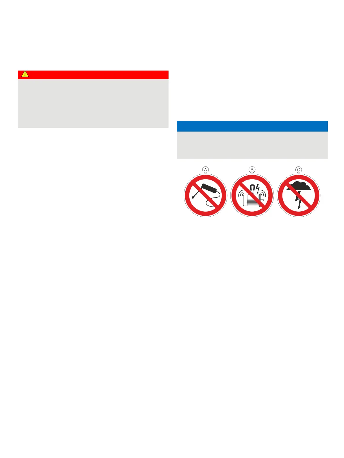
NOTICE
Temperature transmitter damage!
Overvoltage, overcurrent and high-frequency interference
signals on the supply connection as well as sensor connection
side of the device can damage the temperature transmitter.
A Do not weld
B No high-frequency interference signals / switching operations of large
consumers
C No overvoltage due to lightning
Figure 14: Warning signs
Overcurrent and overvoltage can occur through for example
welding operations, switching operations of large electric
consumers, or lightning in the vicinity of the transmitter, sensor,
as well as connector cables.
Temperature transmitters are sensitive devices on the sensor
side as well. Long connector cables to the sensor can encourage
damaging interference. This can already happen if temperature
sensors are connected to the transmitter during installation, but
are not yet integrated into the system (no connection to the
supply isolator / DCS)!

 Loading...


