ABB
12
Uniswitch Operation and
Maintenance Manual
UNIS14GB 05-02
The withdrawable assembly establishes the mechanical connection
between the cubicle and the circuit-breaker. The fixed part is connected
to the cubicle by forking, which is form-coded on both sides.
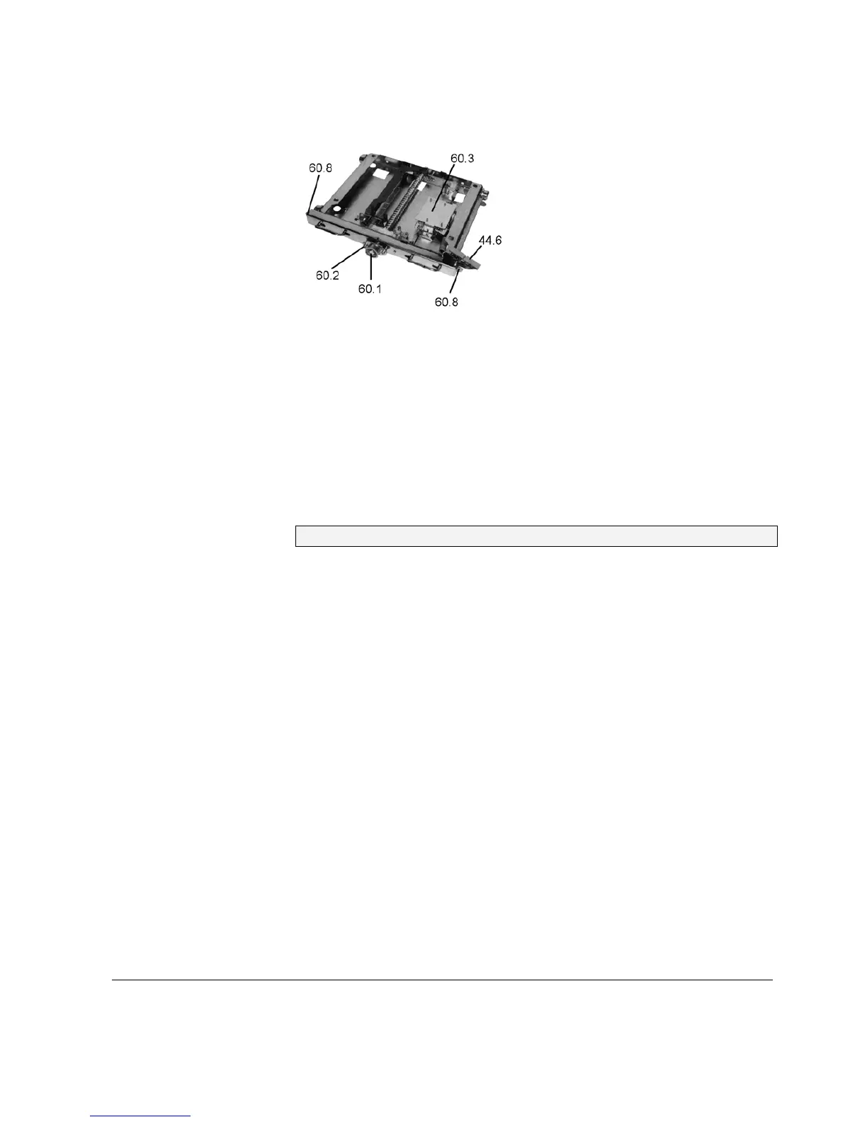
Figure 3.6
Withdrawable assembly for circuit-breaker, with auxiliary switches.
The moving part with the circuit-breaker is moved manually by means of
a spindle (60.1), between the service or test/disconnected positions with
the front doors closed. Service and test/disconnected positions are set
precisely by means of auxiliary switches (60.3), which indicate the final
position reached and the angular position of the spindle.
The rollers and travel rails (12.1) (Figure 3.10), which are bolted onto
the cubicle, establish the earthing connection between the withdrawable
part and the cubicle.
Withdrawable parts of the same design are interchangeable.