ABB
32
Uniswitch Operation and
Maintenance Manual
UNIS14GB 05-02
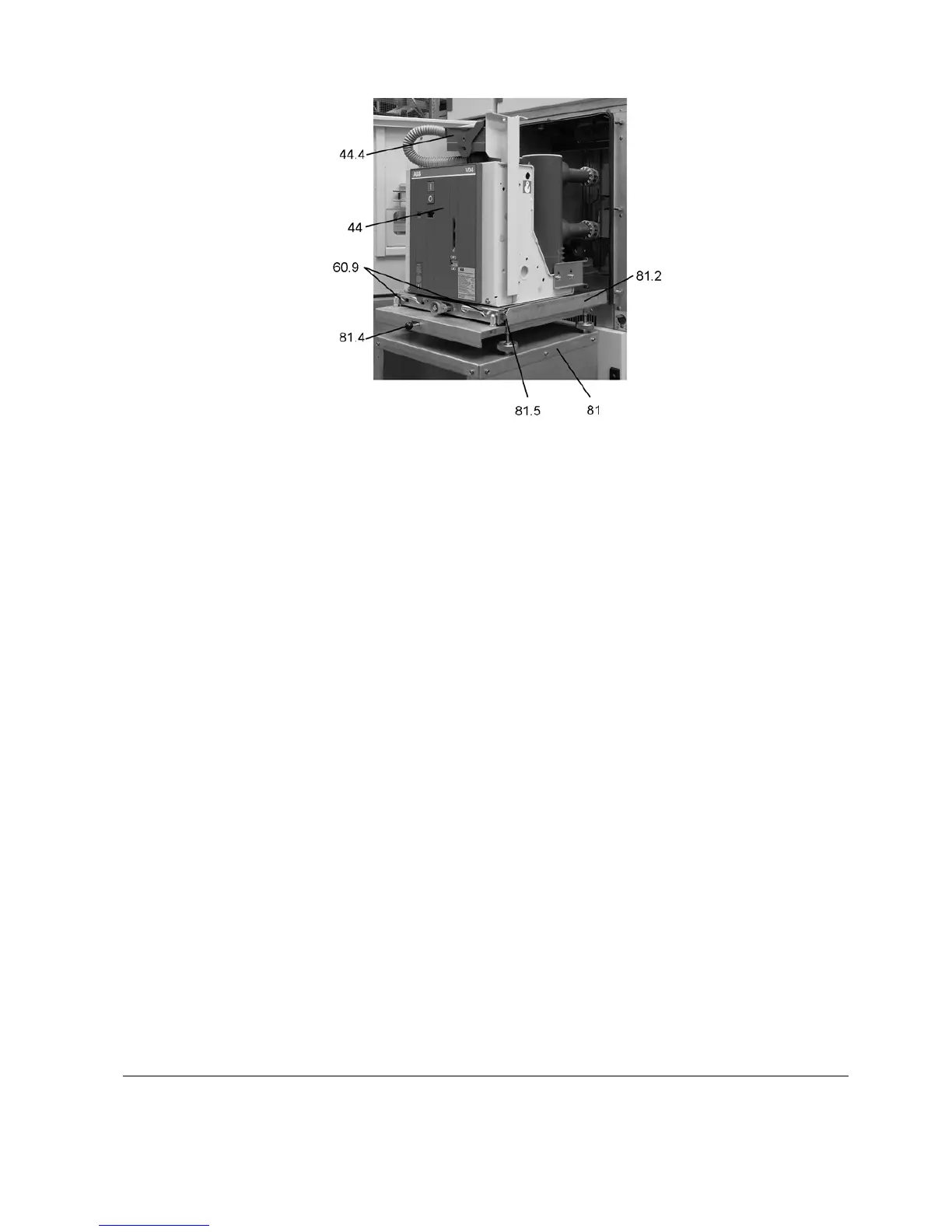
Figure 4.12
Withdrawable part standing on service truck and secured by the catches.
Instructions 1) Open the door of the HV-compartment.
2) Release control wiring plug (44.4) (Figure 4.9) and place it in the
storage position on the withdrawable part.
3) Position service truck (81) with guide pins (81.1) (Figure 4.10) of the
adjustable bench top, at the correct height, facing the cubicle front,
and allow catch (81.3) (Figure 4.10) to engage.
4) Move sliding handles (60.9) inwards against the springs to release
withdrawable part (44), draw the withdrawable part out onto the
service truck and secure it in the catches (81.5) on the truck.
5) Press release lever (81.4) (at the front, underneath the bench top)
and release the service truck from the switchgear cubicle.
4.4.1.4 Insertion from the service truck into the test/disconnected position
Instructions
• Carry out the procedure described in 4.4.1.3 for withdrawal in
reverse order.