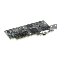
Mechanical installation
The mechanical installation of the device inside the inverter is a simple
operation which does not require any particular tools.
However, due to the thickness of the casing, a specic adapter, which is supplied with the
device, is required when installing on inverter models UNO-2.0/2.5-I-OUTD and TRIO-
5.8/7.5/8.5-TL-OUTD.
Refer to the inverter documentation to identify the position and shape of
the expansion slot to be used (single or double connector).
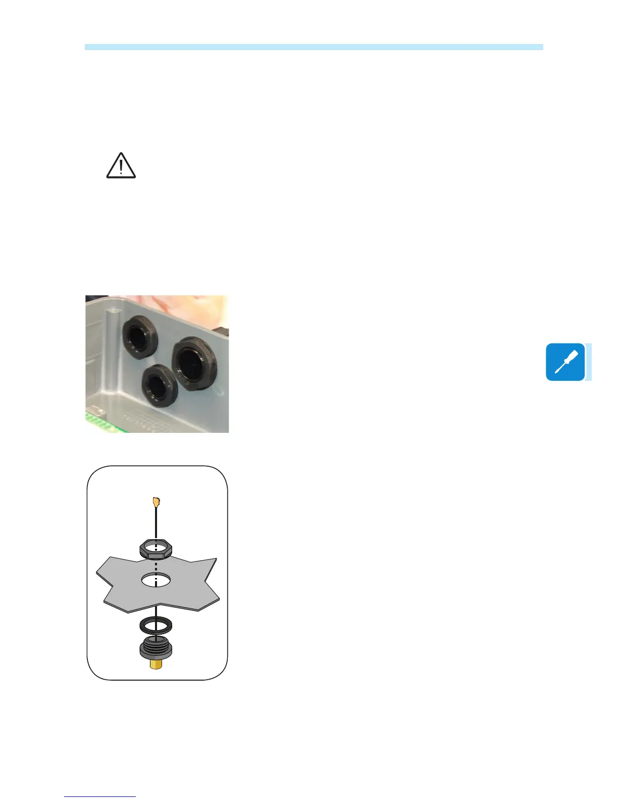
Installation of the antenna
The antenna must be installed on the outside of the inverter in the place
of one of the service cable glands (size M20).
For installations on inverters for which an adapter is not required,
proceed as follows:
• Remove one of the M20 service cable glands from the inverter (using
a 25mm wrench).
• Pass the antenna connection cable into the inverter through the M20
cable gland opening, the gasket, the plastic locking nut.
• Secure the antenna connector (RP-SMA female) to the inverter using
the plastic locking nut supplied (tightening torque 5 Nm).
• Screw in the Wi-Fi antenna to the connector (RP-SMA female)
Installation without adapter