System Overview
OPTIS™ Integrated Next Operation and Maintenance Manual – 600173796 Rev. A 21
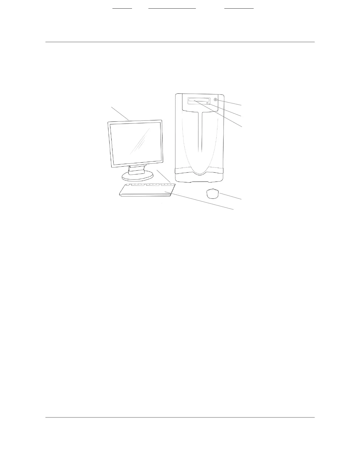
OPTIS Integrated Next - Cabinet and Control Room Components
Figure 3. OPTIS Integrated Next - Cabinet and Control Room Components
Note:
• Standby button / indicator: Activate to put the system into Standby state
(indicator is off). Press to exit Standby state and turn on the system
(indicator turns green).
• A potential equalization conductor post (located on the back of the
system cabinet, compliant to IEC 60601- 1:2005 cl.8.6.7) provides a
direct connection between the electrical equipment and the potential
equalization buss bar of the electrical installation.
2. Standby
button/indicator
3. CD/DVD eject button
4. CD/DVD tray
5. Wired mouse
6. Wired keyboard with
USB ports
State: Released Date: 2021.03.01 22:19 GMT Effectivity: Upon Release