INSTALLATION
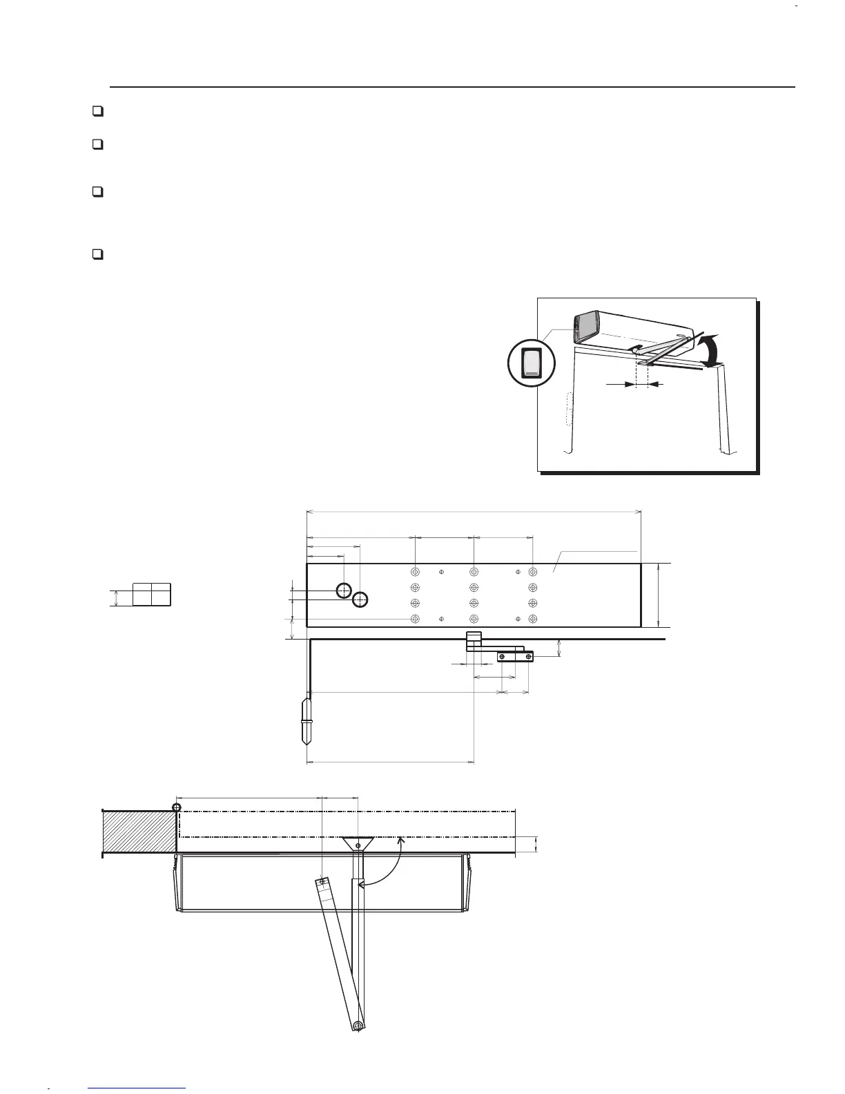
Drill the installation holes as shown in the drilling diagrams.
Attach the door operator to the mounting plate with four screws M8 x 25
provided.
Use the mounting plate delivered with the door operator ensuring the installation
base is level and securely fixed. Minimum wall thickness
should be 5 mm if the door frame is of metal construction.
The door operator's frame and mounting plates are provided with wiring holes
enabiling concealed wiring.
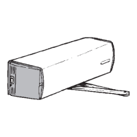
a) Push function
drilling diagrams
- use mounting plate DA100
- frame depth max. 150 mm with standard
arm 7281 or DA140, and 150-250 mm with standard
arm 7282 or DA141
- sliding arm 7611 can be used in lightweight
doors (max. opening angle 90 )
- arms DA140 and DA141 are also provided
with inch machine screws
o
IO
90
o
70
Opening angle
max. 100
o
ARM W
7281 0 - 150
7282 150 - 250
284 70
W
90°
5
EX
EX
DA100
YZY Z
Y
Z
95 60
95 60
85 5085 50
75 4075 40
65 3065 30
55 2055 20
45 1045 10
35 035 0
100
108
100
184
25
70
331.5
30
45
568
284
89
62
32.5
15