17
6.22 Receiver Settings -i-BUS Settings
The i-BUS SET(i-BUS setting) function is a unique and powerful serial communication protocol
system provided by Absima. It can be output to any channel by setting.For receivers with i-BUS
interface and corresponding accessories, see the description of serial bus receivers for details.
Function settings:
1. The transmitter and receiver are completed successfully;
2. Connect the input cable of the i-BUS receiver to the SERVO port of the receiver;
3. Connect the servo to the C1-C4 ports of the i-BUS receiver;
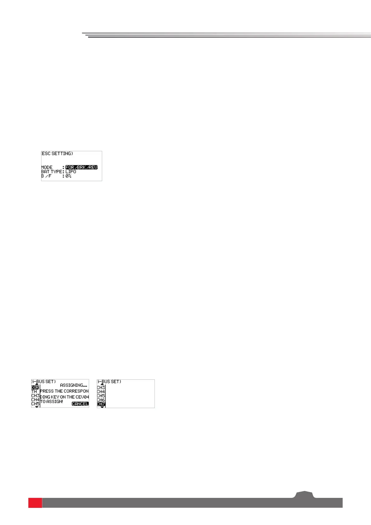
4. Turn on the transmitter to enter the i-BUS SET interface, and select the channel to be assigned;
if the channel is incorrect, select "CANCEL" to re-set;
Note: If the interface prompts to set the RF type to "ANT TWO WAY" first, set the RF type to ANT
TWO WAY first.
5. Press the corresponding button on the i-BUS receiver. After the setting is successful, the system
will pop up a pop-up window showing the interface number of the currently selected channel
assigned to the i-BUS receiver.
6. Repeat the above steps to set more channels.
Note: If the receiver is overloaded, please supply power separately to prevent the wire from being
burnt out due to excessive current.
There are two braking modes as follows: the first mode is FOR/BRK/REU that means, the device
moves forward when pressing the trigger for acceleration; it is braked when pulling the trigger
backward and then reverses when releasing the trigger to the neutral position and then pulling
it backward again; and the second mode is forward/reverse that means, the device moves forward
when pressing the trigger for acceleration, and it reverses immediately when pulling the trigger
backward.These two modes can be set according to actual needs.
Function settings:
1. In the ESC SET menu, select the item to be adjusted by pressing the UP/DOWN key and press the
OK key for editing. Set the desired value by pressing the UP/DOWN key and press the OK key to
confirm the adjustment.
2. After that, carry out a test to confirm that all set channel outputs are functioning as expected.
6.23 Model
The MODEL menu is used for model management. It includes four options: select model, model
name, copy model and reset model.
SELECT: The transmitter can save up to 20 sets of model data, and you can call out one set of model
data at any time and use it as needed.
NAME: The name of the model you select can be edited and changed.