17 SM01P
NOTE
If TB-13A, TB-13B, and TB-13E are all programmed to select speed references, and
two or three of the terminals are closed to TB-11, the higher terminal has priority and
will override the others. For example, if TB-13A is programmed to select 0-10VDC,
and TB-13E is programmed to select PRESET SPEED #3, closing both terminals
to TB-11 will cause the drive to respond to PRESET SPEED #3, because TB-13E
overrides TB-13A.
The exception to this is the MOP function, which requires the use of TB-13B and TB-
13E. This leaves TB-13A to be used for some other function. If TB-13A is programmed
for a speed reference, and TB-13A is closed to TB-11, TB-13A will override the MOP
function.
10.7 Drive Status Digital Outputs
There is one Form A relay at terminals TB-16 and TB-17. The relay contacts are rated 3
amps at 250 Vac.
Terminal TB-13E can also be configured as a digital output. This output circuit is a current-
sourcing type rated at 12 VDC and 50 mA maximum.
The Form A relay and digital output can be programmed to indicate any of the following:
RUN, FAULT, INVERSE FAULT, FAULT LOCKOUT, AT SPEED, ABOVE PRESET SPEED
#3, CURRENT LIMIT, AUTO SPEED MODE, and REVERSE. Refer to Parameters 06
and 12 in Section 15, DESCRIPTION OF PARAMETERS.
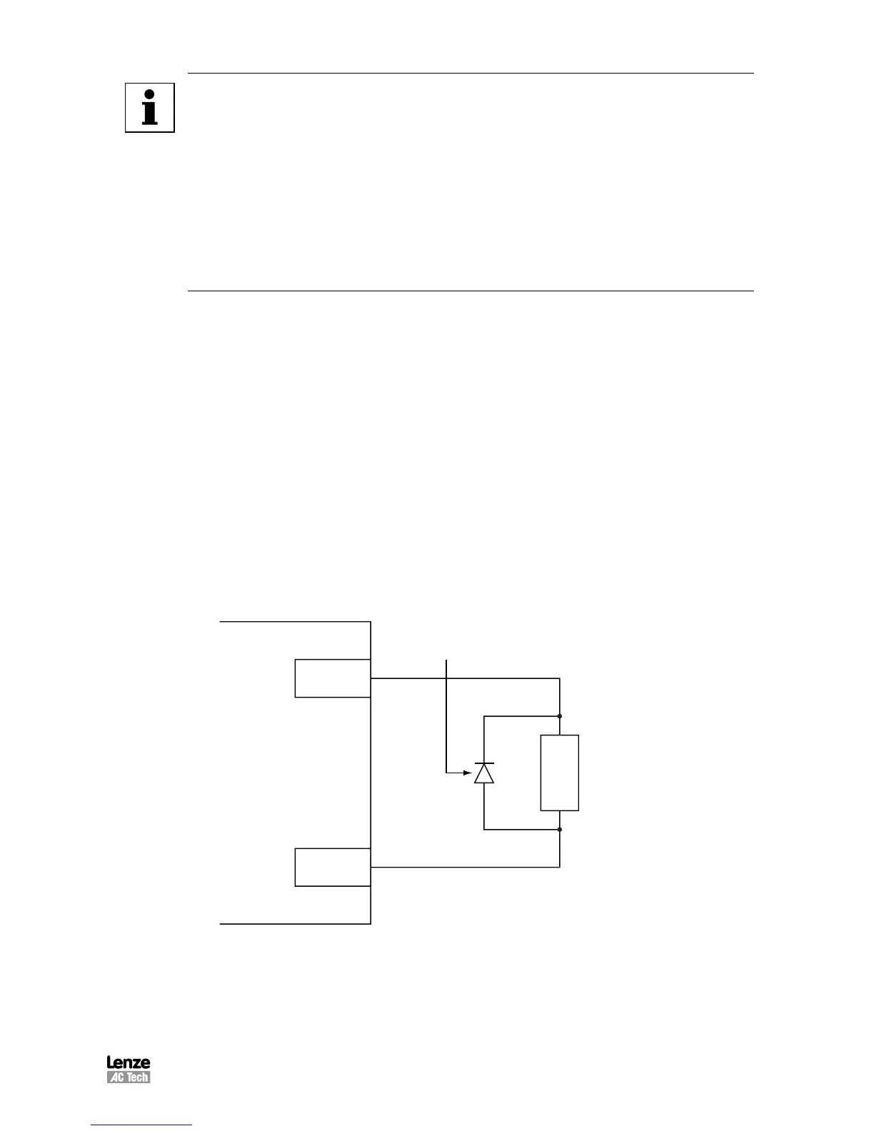
The diagram below illustrates how TB-13E, when configured as a digital output, can be
used to drive an external relay:
Diode Snubber
(1N4148 or Equivalent)
TB-2
TB-13E
Relay Coil
SCL/SCM Terminal Strip
TB-13E used to Drive an External Relay