EasyManua.ls Logo

Accuphase C-2810 - User Manual

Accuphase C-2810
38 pages
Go to English
Print Icon
To Next Page IconTo Next Page
Loading...
Precision Preamplifire
C-2810
Service Information
STARTIN G WITH SERIAL No. F6Y001
Attention mark indicating critical components for safety.
Replacement must be made with identical parts of special part number.
このマークのついている部品は、安全上重要な部品です。
必ず指定されている部品番号の部品を使用して下さい。
Authorized Technical Service Only
サービス資格のある技術者が使用して下さい
These servicing instructions are for use by qualified personnel only.
To reduce the risk of electric shock do not perform any servicing
other than that contained in the operating instructions unless you are
qualified to do so. Refer all servicing to qualified service personnel.
ここに記載したサービスに関する指示事項は、サービスに関する資格を
有する者のみが使用するものです。感電防止の観点から、サービス資格
を有していない方は、取扱指示事項以外のサービスは絶対に行わないよ
うにして下さい。
CAUTION /
注意
C-2810
Schematic Diagram
回路図
Question and Answer IconNeed help?

Do you have a question about the Accuphase C-2810 and is the answer not in the manual?

Accuphase C-2810 Specifications

General IconGeneral
BrandAccuphase
ModelC-2810
CategoryAmplifier
LanguageEnglish

Summary

Service Information and Safety Guidelines

Authorized Technical Service Only

Instruction for qualified personnel only to perform servicing.

General Safety Precautions

Warning about electric shock and servicing procedures.

AC Line Voltage Selection Caution

Guidance on changing the unit's voltage setting and fuse selection.

Unit External Features

Surface Parts Identification

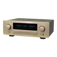
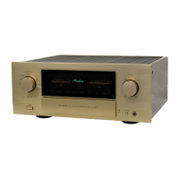
Diagrams identifying external components and their part numbers.

Maintenance and Repair Procedures

Wood Case Crack Prevention

Procedure to prevent scratches on the wood case using a protection sticker.

Headphone Hum Noise Countermeasure

Steps to reduce hum noise during headphone use by modifying wiring.

Selector LED Lighting Fix

Method to insulate connections to prevent selector LED lighting issues.

Power Supply ON Noise Prevention

Procedure to prevent shock noise when turning on the unit with volume raised.

Special Operation Mode Setup

Instructions for setting special operational modes and factory shipping positions.

System Architecture and Schematics

Master Circuit Diagram Overview

Overall block diagram showing interconnections between main assemblies.

Balance Input Amp Schematic

Detailed circuit diagram for the balance input amplifier assembly.

Output Stage Assembly Schematics

Schematics for Balance Output, Volume, Attenuator, and Power Switch assemblies.

Signal Path Assembly Schematics

Schematics for Recording Amp, Voltage Selector, Head Phone, Input Selector, and Selector LED assemblies.

VI(1) Assembly Schematic

Detailed circuit diagram for the VI(1) amplifier assembly.

IV Assembly Schematic

Detailed circuit diagram for the IV amplifier assembly.

Filter Amp and Power Supply Schematics

Schematics for the Filter Amplifier and Power Supply assemblies.

Core Board Schematics

Schematics for the Mother Board and Connector Board assemblies.

Control Assembly Schematics

Schematics for the Switch and Logic assemblies.

Interface Assembly Schematics

Schematics for the Tact Switch and Display assemblies.

System Block Diagrams

Overall System Block Diagram

High-level block diagram illustrating signal flow and component interaction.

AD-2800 Option Block Diagram

Block diagram for the optional Phono Equalizer Unit AD-2800.

Technical Specifications

Detailed Performance Specifications

Comprehensive list of measured electrical and physical specifications.

Related product manuals