EasyManua.ls Logo

Accuphase E-550 - User Manual

Accuphase E-550
33 pages
Print Icon
To Next Page IconTo Next Page
Loading...
Attention mark indicating critical components for safety.
Replacement must be made with identical parts of special part number.
このマークのついている部品は、安全上重要な部品です。
必ず指定されている部品番号の部品を使用して下さい。
Authorized Technical Service Only
These servicing instructions are for use by qualified personnel only.
To reduce the risk of electric shock do not perform any servicing
other than that contained in the operating instructions unless you are
qualified to do so. Refer all servicing to qualified service personnel.
ここに記載したサービスに関する指示事項は、サービスに関する資格を
有する者のみが使用するものです。感電防止の観点から、サービス資格
を有していない方は、取扱指示事項以外のサービスは絶対に行わないよ
うにして下さい。
CAUTION /
回路図
Bi-lingual
Question and Answer IconNeed help?

Do you have a question about the Accuphase E-550 and is the answer not in the manual?

Accuphase E-550 Specifications

General IconGeneral
BrandAccuphase
ModelE-550
CategoryAmplifier
LanguageEnglish

Summary

Important Safety Information

Authorized Technical Service Only

Warning that only qualified personnel should perform servicing.

CAUTION; 注意

Safety warning regarding electric shock and servicing procedures.

EXPLANATION OF SURFACE PARTS

Surface Component Identification Diagram

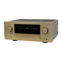
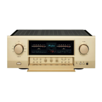
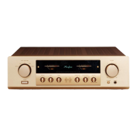
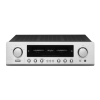
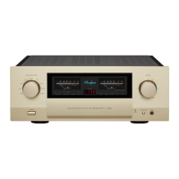
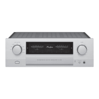
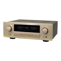
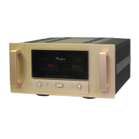
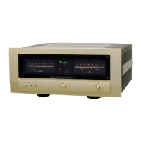
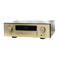
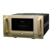
Diagram labeling external parts of the Accuphase E-550 amplifier.

FRONT VIEW (前面)

Front Panel Component Identification

Detailed labeling of components on the front panel of the unit.

REAR VIEW (後面)

Rear Panel Component Identification

Detailed labeling of components on the rear panel of the unit.

TOP VIEW (上面)

Top View Component Identification

Diagram labeling internal components visible from the top of the unit.

BOTTOM VIEW (底面)

Bottom View Component Identification

Diagram labeling internal components visible from the bottom of the unit.

FRONT VIEW (Sub-chassis side)

Sub-chassis Front View Component Identification

Diagram labeling components on the sub-chassis side of the front panel.

Explanation of Front-panel back view

Front Panel Back View Component Identification

Diagram labeling components on the back side of the front panel assembly.

MISCELLANEOUS (本体その他使用部品)

Miscellaneous Parts and Accessories List

List of various spare parts, consumables, and accessories for the unit.

Remote Commander RC-200 Operation

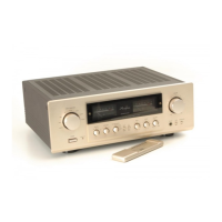
Diagram and description of the RC-200 remote control functions.

Balance Input Amp Assembly (712-0097-00)

Balance Input Amplifier Component Breakdown

Detailed list of components and part numbers for the Balance Input Amplifier Assy.

IV Assembly (713-0014-00)

IV Assembly Component Breakdown

Detailed list of components and part numbers for the IV Assy.

VI Assembly (713-0013-00)

VI Assembly Component Breakdown

Detailed list of components and part numbers for the VI Assy.

In-rush Protector Assembly

In-Rush Protector Assembly Component Breakdown

Detailed list of components and part numbers for the In-Rush Protector Assy.

Mother Board Assembly (716-0729-00)

Mother Board Assembly Component Breakdown

Detailed list of components and part numbers for the Mother Board Assy.

Switch Assembly (716-0730-00)

Switch Assembly Component Breakdown

Detailed list of components and part numbers for the Switch Assy.

IO Relay Assembly (716-0731-00)

IO Relay Assembly Component Breakdown

Detailed list of components and part numbers for the IO Relay Assy.

Volume Assembly (716-0732-00)

Volume Assembly Component Breakdown

Detailed list of components and part numbers for the Volume Assy.

Head Phone Assembly (716-0733-00)

Head Phone Assembly Component Breakdown

Detailed list of components and part numbers for the Head Phone Assy.

Input Selector Assembly (716-0734-00)

Input Selector Assembly Component Breakdown

Detailed list of components and part numbers for the Input Selector Assy.

Connector Board Assembly (716-0735-00)

Connector Board Assembly Component Breakdown

Detailed list of components and part numbers for the Connector Board Assy.

Power Amp Assembly (717-0087-00)

Power Amp Assembly Component Breakdown

Detailed list of components and part numbers for the Power Amp Assy.

Power Supply Assembly (719-0058-00)

Power Supply Assembly Component Breakdown

Detailed list of components and part numbers for the Power Supply Assy.

Protection Assembly (720-0075-00)

Protection Assembly Component Breakdown

Detailed list of components and part numbers for the Protection Assy.

Logic Assembly (721-0081-00)

Logic Assembly Component Breakdown

Detailed list of components and part numbers for the Logic Assy.

Receiver Assembly (721-0082-00)

Receiver Assembly Component Breakdown

Detailed list of components and part numbers for the Receiver Assy.

Display Assembly (723-0116-00)

Display Assembly Component Breakdown

Detailed list of components and part numbers for the Display Assy.

Metar Lamp Assembly (723-0117-00)

Metar Lamp Assembly Component Breakdown

Detailed list of components and part numbers for the Metar Lamp Assy.

Selector LED Assembly (723-0118-00)

Selector LED Assembly Component Breakdown

Detailed list of components and part numbers for the Selector LED Assy.

Service Information (No. E550-001)

Subject: LINE BAL Input Switching Issue

Describes an issue where LINE BAL input switching is not possible.

Details: Connector K2;4 pin Issue

Explains the problem with the Balance Input Amp Assy connector K2/4 pin.

Preparation Parts: Jumper Wire

Lists the required jumper wire for the repair procedure.

Service Procedure: Wire Jumper

Step-by-step instructions for wiring a jumper for the repair.

Service Information (No. E550-002)

Subject: VI Assy Left-Right Mounting Position

Addresses the issue of incorrect left-right mounting of the VI Assembly.

Details: VI Assy Mounting Position Reversed

Explains that the VI Assy is mounted in a reversed left-right position.

Service Information (No. E550-003)

Subject: Noise Countermeasure for Volume

Details measures to address noise issues related to the volume control position.

Details: IC Fault Noise Issue

Explains that noise may occur due to an IC fault at specific volume positions.

Preparation Parts: IC and Cool Sheet

Lists the IC and Cool Sheet required for the noise countermeasure.

Service Procedure: IC Exchange

Step-by-step instructions for exchanging the IC to resolve noise.

CIRCUIT ADJUSTMENT (回路調整)

Bias Current Adjustment for Power Amp

Procedure for adjusting the bias current for the power amplifier.

Meter Calibration

Procedure for calibrating the unit's meters, including peak and -30dB levels.

Caution for AC line Voltage Selection

AC Voltage Selection Procedure

Step-by-step guide for changing the unit's AC input voltage setting.

Voltage Selection Table

Table detailing fuse, connector, and power cord settings for different voltage selections.

PACKING (梱包図)

Packaging Diagram and Contents

Illustration showing how the unit and its accessories are packed.

E-550 MASTER CIRCUIT DIAGRAM

Master Circuit Block Diagram

High-level block diagram illustrating the overall signal flow and interconnections.

BALANCE INPUT AMP ASSY (712-0097-00)

Balance Input Amplifier Schematic Diagram

Detailed schematic diagram of the Balance Input Amplifier Assy.

VI ASSY (713-0013-00)

VI Assembly Schematic Diagram

Detailed schematic diagram of the VI Assy.

IV ASSY (713-0014-00)

IV Assembly Schematic Diagram

Detailed schematic diagram of the IV Assy.

VOLUME ASSY (716-0732-00)

Volume Assembly Schematic Diagram

Detailed schematic diagram of the Volume Assy.

HEAD PHONE ASSY (716-0733-00)

Head Phone Assembly Schematic Diagram

Detailed schematic diagram of the Head Phone Assy.

IN-RUSH PROTECTOR ASSY

In-Rush Protector Assembly Schematic Diagram

Detailed schematic diagram of the In-Rush Protector Assy.

INPUT SELECTOR ASSY (716-0734-00)

Input Selector Assembly Schematic Diagram

Detailed schematic diagram of the Input Selector Assy.

MOTHER BOARD ASSY (716-0729-00)

Mother Board Assembly Schematic Diagram

Detailed schematic diagram of the Mother Board Assy.

RECEIVER ASSY (721-0082-00)

Receiver Assembly Schematic Diagram

Detailed schematic diagram of the Receiver Assy.

SWITCH ASSY (716-0730-00)

Switch Assembly Schematic Diagram

Detailed schematic diagram of the Switch Assy.

CONNECTOR BOARD ASSY (716-0735-00)

Connector Board Assembly Schematic Diagram

Detailed schematic diagram of the Connector Board Assy.

SELECTOR LED ASSY (723-0118-00)

Selector LED Assembly Schematic Diagram

Detailed schematic diagram of the Selector LED Assy.

POWER AMP ASSY (717-0087-00)

Power Amp Assembly Schematic Diagram

Detailed schematic diagram of the Power Amp Assy.

PROTECTION ASSY (720-0075-00)

Protection Assembly Schematic Diagram

Detailed schematic diagram of the Protection Assy.

METER LAMP ASSY (723-0117-00)

Meter Lamp Assembly Schematic Diagram

Detailed schematic diagram of the Meter Lamp Assy.

POWER SUPPLY ASSY (719-0058-00)

Power Supply Assembly Schematic Diagram

Detailed schematic diagram of the Power Supply Assy.

LOGIC ASSY (721-0081-00)

Logic Assembly Schematic Diagram

Detailed schematic diagram of the Logic Assy.

Related product manuals