Machine Maintenance 3-35
Removing the Upper Case Assembly 0
1. Perform the “Removing the Mainboard” procedure described on page 3-27.
2. Perform the “Removing the LED Indicator” procedure described on page 3-34.
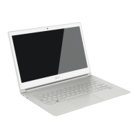
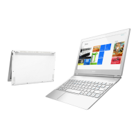
3. Tilt the upper case until it is approximately at a 45° angle with the LCD assembly.
Figure 3-53. Upper Case Assembly
4. Remove the four screws securing the upper case assembly to the LCD hinges.
Figure 3-54. Upper Case Screws – LCD Hinges
Table 3-54. Screws
Step Screw Quantity Screw Type
Upper Case Disassembly M2 x L4 4

 Loading...


