Acer Service Manual
13
1.5.2 Hot Key Operation
HOT KEY OPERATION
FUNCTION
AUTO ◄ ► MENU
POWE
R
DESCRIPTION
FACTORY
MODE
● ● ON
Press [AUTO] & [MENU] at the same
time, and then press [POWER] for DC
power on. OSD menu will be shown
with “F” on the left top. Select “F” for
entering factory mode.
1.6 Burn-in (Aging) Pattern
1.6.1 Burn-in patterns are: full Red, Green, Blue, White and Black
1.6.2 Stop burn-in pattern by providing with video signal from D-sub or DVI-D connector
1.6.3 Enter or exit burn-in mode by setting “burn-in” to be “on” or “off” in the factory mode
1.7 Warm Up
All test units have to be done warm up after at least 2 hours in a room with temperature of 40±5°C. (Except
particular requirement)
2. INPUT SIGNAL
2.1 Video Signal Input
2.1.1 VESA Analog
The video input consists of red, green, and blue signals. The video signals are analog levels, where 0V
corresponds to black and 700mV is the maximum signal amplitude. Input impedance of video pins is 75
ohm ±1%.
Sync signal input
The capability of sync signal inputs shall include separate sync. Input impedance: 2k2 ohms the signals
are defined as follow:
Separate sync TTL level, Positive/Negative
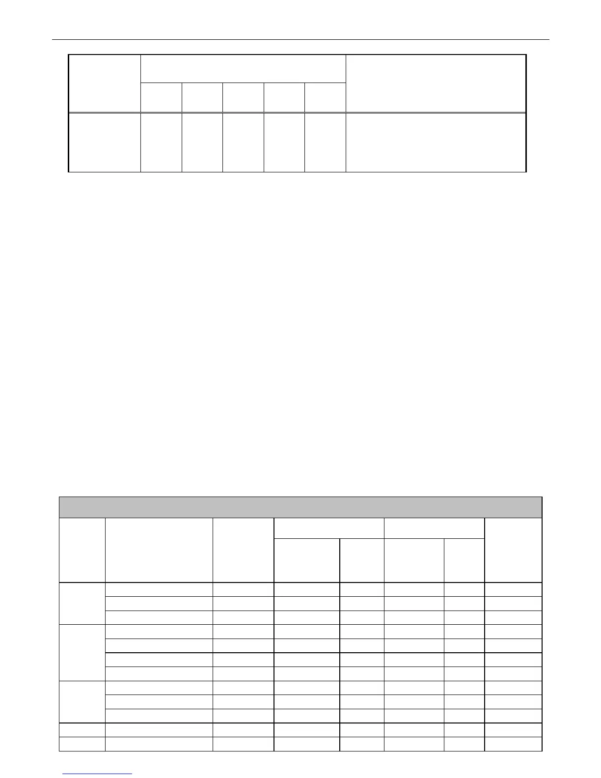
2.1.2 Input signal mode
PRESET TEST MODE TIMING
VESA MODES
Horizontal Vertical
Mode Resolution Total
Nominal
Frequency
+/-0.5KHz
Sync
Polarity
Nominal
Frequency
+/-1Hz
Sync
Polarity
Nominal
Pixel Clock
(MHz)
640*480@60Hz 800*525 31.469 N 59.941 N 25.175
640*480@72Hz 832*520 37.861 N 72.809 N 31.500
VGA
640*480@75Hz 840*500 37.500 N 75.000 N 31.500
800*600@56Hz 1024*625 35.156 P 56.250 P 36.000
800*600@60Hz 1056*628 37.879 P 60.317 P 40.000
800*600@72Hz 1040*666 48.077 P 72.188 P 50.000
SVGA
800*600@75Hz 1056*625 46.875 P 75.000 P 49.500
1024*768@60Hz 1344*806 48.363 N 60.004 N 65.000
1024*768@70Hz 1328*806 56.476 N 70.069 N 75.000
XGA
1024*768@75Hz 1312*800 60.023 P 75.029 P 78.750
1152*864@75Hz 1600*900 67.500 P 75.000 P 108.000
1280*960@60Hz 1800*1000 60.000 P 60.000 P 108.000
 Loading...