HARDWARE MANUAL
23
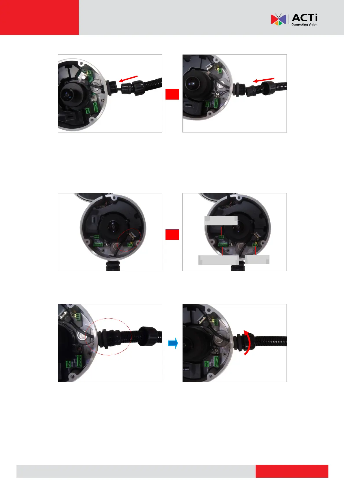
7. Insert the Ethernet cable and other cables (if any) through the conduit gland body.
Ethernet Cable Only Ethernet and External Power Adapter Cable
8. Connect the Ethernet cable to the Ethernet port of the camera. If connecting other cables,
such as an external power adapter, audio in/out or DI/DO devices, connect the terminal
blocks at this point and connect them to the corresponding connectors of the camera (see
Other Connections on page 26 for more information).
9. Insert the sealing rubber into the conduit gland body and attach the clamping nut to
complete the cable solution.
NOTE: Make sure the clamping nut is tightly attached to the conduit gland body.
10. Proceed with see Step 4: Install the Camera to the Surface on page 24.
Digital Input / Output
(DI/DO) Connector
Audio Input /
Output Connector