8
Operation Manual - (CP05 / CP10) Commercial Control Interface
Doc. No. 0525-031 Ver. 3 190308
INITIALISATION DISPLAYS - STATUS INDICATIONS
POWER-UP (INITIALIZATION DISPLAYS COMPRESSORS & REVERSING VALVES
STATUS INDICATIONS
Display Progression Display Progression
Room T. :
22.5
o
C
o
C
Supply T. :
Comp Rev Vlv
10:20 Unit: Unit ON
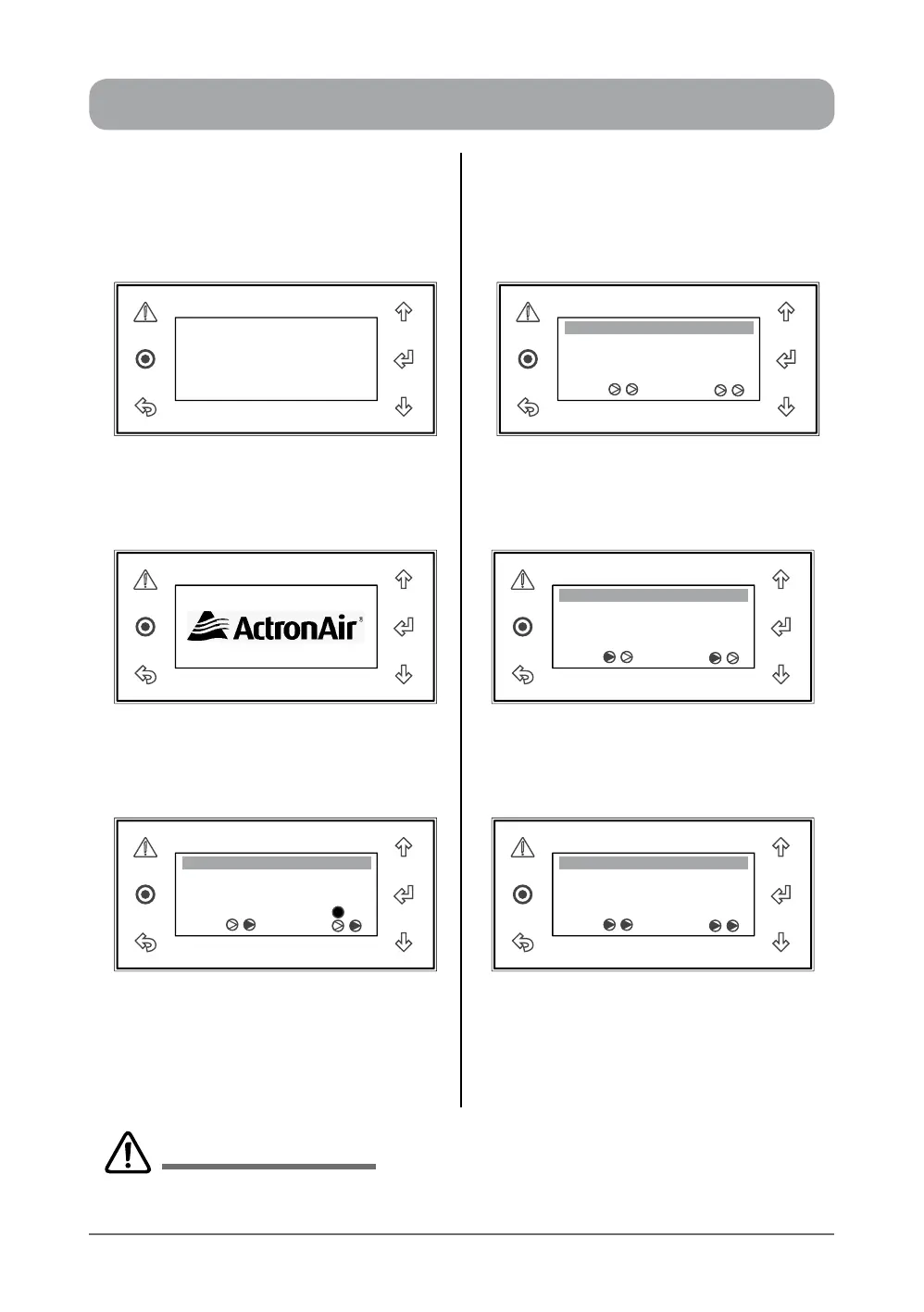
When the control interface is powered "ON"
for the rst time, The display will be blank for
5 - 10 seconds
Both Compressors & Reversing Valves are
Off, as indicated by clear triangles
Room T. :
23.7
o
C
o
C
Supply T. :
Comp Rev Vlv
10:20 Unit: Unit ON
ActronAir logo will then be displayed for the
next 5 - 10 seconds
Compressor 1 & Reversing Valve 1 are On.
(System in Heat Mode), rst triangles are
darkened
Room T. :
23.7
o
C
o
C
Supply T. :
Comp Rev Vlv
Defrost
10:20 Unit: Unit ON
Room T. :
23.7
o
C
o
C
Supply T. :
Comp Rev Vlv
10:20 Unit: Unit ON
System Screen (default) provides an
overview of system status, showing the
Room Temperature, Supply Temperature,
Compressors, Reversing Valves ON/OFF
status and System Defrost indicator.
Compressors 1 & 2 and Reversing Valves
1 & 2 are On. (Systems are in Heat Mode),
all triangles are darkened
Displays for two compressors & reversing valves are shown above for illustration purposes only. The number
of compressors / reversing valves displayed will depend on the air conditioning system model.
IMPORTANT NOTES
 Loading...