EN • 11
ENGLISHFRANCAISNEDERLANDSESpAñoLITALIANoDEuTSCH
664Y0200.C
CircuitdiagramofACVcontrolkits
B2. Temperature sensor
B9. Outdoor sensor
B5. Analog/digital room sensor
P1. Pump
Y1/Y2/N. Servomotor (SSY 319 or SQY 349)
bl. Blue N
n/z. Black Y2
br. Brown Y1
20 19 18 17 16 15 14 13 12 11 10 98765432 1
20 19 18 17 16 15 14 13 12 11 10 98765432 1
bl
bk br
SSY 319 / SQK 349
QAAD50
(QAAD70)
QAC32 QAD22
P1 B5 B9 B3 B2
P1Y1Y2NB5B9B3B2
Pleasecontactyourinstallerforfurtherdetailsabout
this.
GAS CONNECTION
- The boiler is fitted with a 3/4” M connector. It is possible to
connect it to the gas tap.
- The gas connection must be made in accordance with standard
NBN D51-003 and, where applicable, other standards in force
at the place of connection.
- If there is a risk of dirt near the network, fit a gas filter
upstream of the connection.
- Vent the gas pipe and carefully check that all external and
internal boiler pipes are gas tight.
- Check the installation’s gas pressure.
- Check the gas pressure and consumption when commissioning
the appliance.
INSTALLATIoN
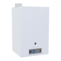
CONTROL KIT
KIT1:ACV13.00/Basic
This basic kit is used to control the hot water circuit outlet
temperature as a function of ambient conditions.
It comprises: a temperature controller with analog clock, a
surfacemounted primary water temperature sensor (-30/130°C),
an outdoor sensor (-30/50°C), a servomotor SSY 319 230 V -
3-pin and intermediate socket.
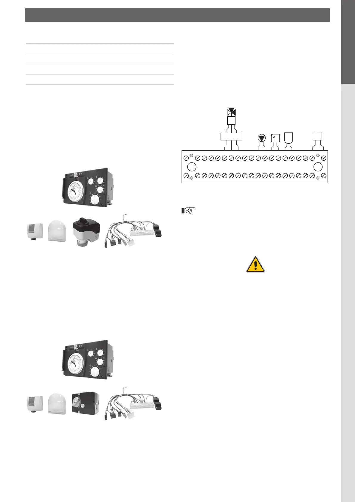
KIT2:ACV13.00/Standard
This Standard kit is used to control the hot water circuit outlet
temperature as a function of ambient conditions.
It comprises: a temperature controller with analog clock, a
surfacemounted primary water temperature sensor (-30/130°C),
an outdoor sensor (-30/50°C), a servomotor SQY 349 230 V -
3-pin and an intermediate socket.
Optionalaccessories
Safety group
Ø 3/4"
Pressure reducing valve
Ø 3/4"
Thermostatic mixer
Ø 3/4"
Expansion vessel
5 litres
 Loading...