EN • 5
ENGLISHFRANCAISNEDERLANDSESpAñoLITALIANoDEuTSCH
664Y0200.C
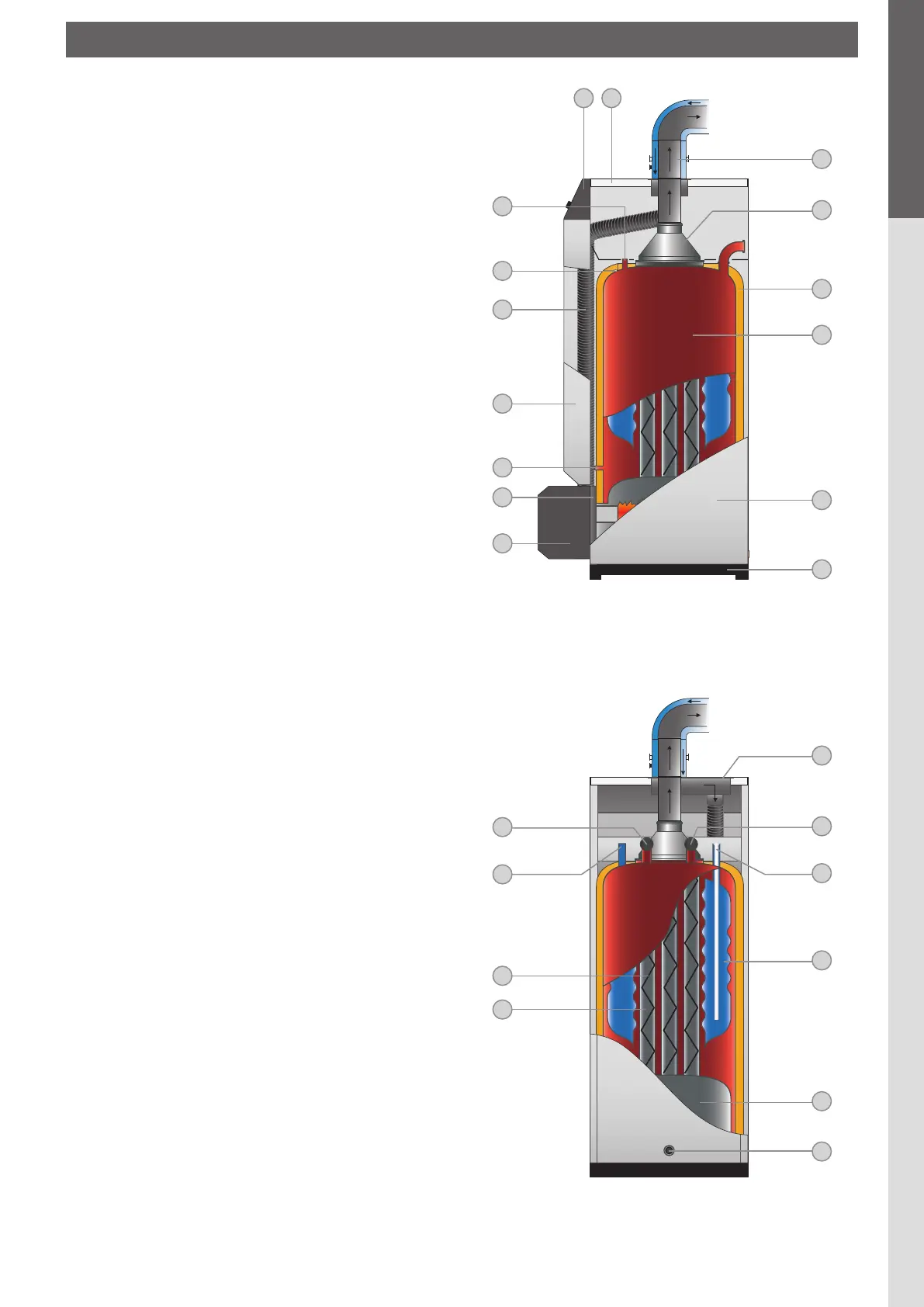
BOILER DESCRIPTION
1. Control panel
2. Detachable casing cover (access to turbulators)
3. Measuring unit with condensate trap (optional)
4. Chimney reducing pipe
5. Polyurethane foam insulation
6. Outer body containing the primary water
7. Side casing
8. Base
9. Burner cover
10. Burner chamber plate
11. Control thermostat bulb (model SV)
Potentiometer bulb (model MV)
12. Detachable front panel
13. Air supply pipe to venturi
14. Manual reset high limit thermostat (103°C)
15. Bulb of the thermal reset high limit thermostat (95°C)
16. Balanced flue adapter
17. Heating return
18. Cold water inlet
19. Inner annular tank containing hot water
20. Combustion chamber
21. Boiler drain cock
22. Flue ways
23. Turbulators
24. Hot water outlet
25. Heating out
3
5
8
7
6
14
13
10
12
11
9
23
1 2
15
4
16
17
18
19
20
21
25
22
24
DESCRIpTIoN
fig. 1 : Right-hand side view of boiler
fig. 2 : Rear view of boiler
 Loading...