EN • 12
ENGLISHFRANCAISNEDERLANDSESpAñoLITALIANoDEuTSCH
664Y0200.C
Br
B
B
Br
Gr
G
Y
Bk
Br
BG 2000-S/SV
Alfa Sprint S/SV
Y/Gr
Br
Br
Or
BBrBr
B
Or
B
Y/Gr
Or
Gr
G
Bk
Y
B
Y/Gr
Y/Gr
11
1
2
3
710
9
8
7
5
4
6
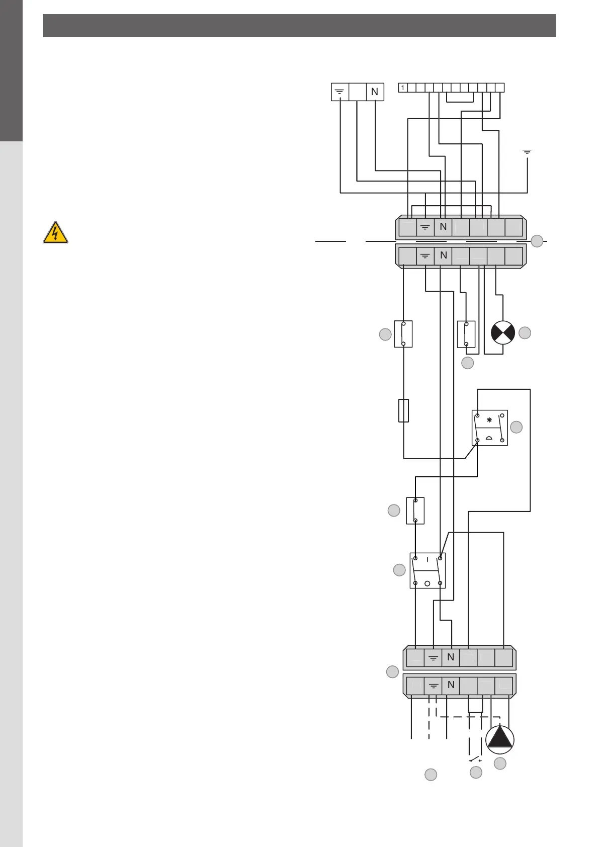
ELECTRICAL CONNECTIONS
Principleofsupply
The boiler operates on a single-phase supply of 230 V/50 Hz.
You should install a control box with main switch and 6 A fuses
externally to the boiler to allow the boiler to be isolated from the
supply for servicing and repairs.
Statutorycompliance
The installation must comply with your local standards and codes
of practice.
Safety
The stainless steel water tank must be provided with a separate
earth.
Theboilermustbeisolatedfromtheelectricalsupply
beforeanyworkiscarriedoutonit.
WiringfortheS/SVboiler(fig.13)
1. Control thermostat (60/90°C)
2. Manual reset high limit thermostat (103°C max.)
3. Main switch
4. Reset
5. Burner shutdown indicator lamp
6. Summer/Winter switch
7. Power supply to boiler
8. Room thermostat ( optional)
9. Heating pump connection
10. Boiler electrical supply connection (6-pin plug)
11. Burner connection (7-pin plug)
WiringfortheM/MVboiler(fig.14)
1. Potentiometer (60/90°C)
2. Manual reset high limit thermostat (103°C max.)
3. Main switch
4. Reset
5. Burner shutdown indicator lamp
6. Summer/Winter switch
7. Power supply to boiler
8. Room thermostat (optional)
9. Heating pump connection
10. Boiler electrical supply connection (6-pin plug)
11. Burner connection (6-pin plug)
12. Fan connection (PWM and 230 V)
13. NTC sensor
14. Printed circuit board
15. Control / monitoring relay
Keytowiring
B. Blue
Bk. Black
Br. Brown
G. Grey
Gr. Green
Or. Orange
R. Red
V. Violet
W. White
Y. Yellow
Y/Gr. Yellow / Green
AlfaSprintS/SV(fig.13)
INSTALLATIoN
 Loading...