EN • 16
ENGLISHFRANCAISNEDERLANDSESpAñoLITALIANoDEuTSCH
664Y0200.C
OPERATING PRINCIPLE OF THE BURNER
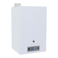
AIR/GASmixturecontrol(fig.12)
The fan draws air in across the venturi. This creates a vacuum
P1 at the venturi neck. The gas valve regulator now reacts to
maintain a difference equal to the amount of the offset between
the pressure at the gas valve outlet P2 and atmospheric
pressure P3 : P2–P3=offset.
If the air flow decreases, P1 rises; the same applies to P2;
now P2>P3; the regulator R moves upwards and restores the
equilibrium P2 – offset = P3; pressure P4 falls and valve C
moves down: the gas flow decreases.
Whatever the speed of the fan therefore, the Air/Gas ratio is
maintained equal to 1 to within the amount of the offset.
The difference in pressure between the neck of the venturi and the
outlet from the gas valve now draws gas through the venturi.
The gas flow adjuster screw is used to adjust the amount of gas
that
is to be injected for a given air flow, and this will determine the
%CO
2 in the flue gas. It is now a very simple matter to control
the burner's power by adjusting the fan speed and the %CO2 to
predefined settings.
Ignitionandflamemonitoring
The control and monitoring relay has a dual function: it ignites
the burner by producing sparks at the ignition electrode, and it
monitors the actual presence of a flame when the gas valve is
open (it measures the ionisation current).
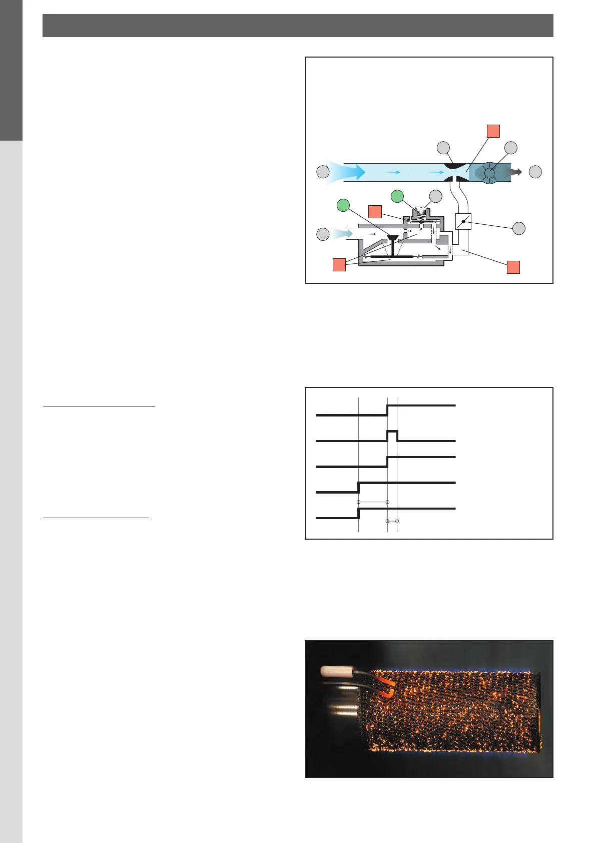
Startingsequence:(fig.13)
The fan starts up when the boiler thermostat/potentiometer
detects a demand for heat. After a 15 second pre-purge the
gas valve opens simultaneously with the ignition. Provided
an ionisation current is detected inside the first 5 seconds,
combustion continues normally until heat is no longer called for.
Otherwise, the gas valve closes and the fan stops; the burner is
now shut down.
Iftheburnershutsdown:
1. The burner indicator lamp lights up on the control panel and
on the burner.
2. Press the burner reset button on the control panel. Turn the
boiler off for several seconds at the main switch, then restart
the the boiler.
Gastube(fig.14)
The air/gas mixture leaving the gas valve/venturi assembly is
propelled into the burner tube.
For Alfa Sprint models M/MV, this tube is covered with metal
fibres (NIT). This enhances the distribution of the flame,
increasing its life and significantly reducing pollutant emissions.
Combustion of the air/gas mixture is also spread uniformly
around the circumference of the tube. The tube is also designed
to withstand propane combustion.
fig. 13 : Starting sequence
Ionisation
Thermostat
Fan
Gas valve opens
Ignition
15s
5s
1. Air
2. Gas
3. Venturi
4. Fan
5. Offset adjuster screw
6. Gas flow adjuster screw (CO2)
7. Air/gas mixture
fig. 12 : Air/gas mixture control
1
7
2
5
R
3
4
6
P1
P2
P3
P4
C
fig. 14 : The NIT gas tube in operation
BuRNER CHARACTERISTICS
 Loading...