Wire it up
Use the diagrams below to help you wire up your piezo. Attach one leg of the piezo to pin A2 on the M0 boards or A1
on the M4 boards, and the other leg to ground. It doesn't matter which leg is connected to which pin. They're
interchangeable!
Circuit Playground Express
Use alligator clips to attach A2 and any one of the GND
to different legs of the piezo.
CPX has PWM on the following pins: A1, A2, A3, A6, RX,
LIGHT, A8, TEMPERATURE, A9, BUTTON_B, D5,
SLIDE_SWITCH, D7, D13, REMOTEIN, IR_RX,
REMOTEOUT, IR_TX, IR_PROXIMITY,
MICROPHONE_CLOCK, MICROPHONE_DATA,
ACCELEROMETER_INTERRUPT,
ACCELEROMETER_SDA, ACCELEROMETER_SCL,
SPEAKER_ENABLE.
There is NO PWM on: A0, SPEAKER, A4, SCL, A5, SDA,
A7, TX, BUTTON_A, D4, NEOPIXEL, D8, SCK, MOSI,
MISO, FLASH_CS.
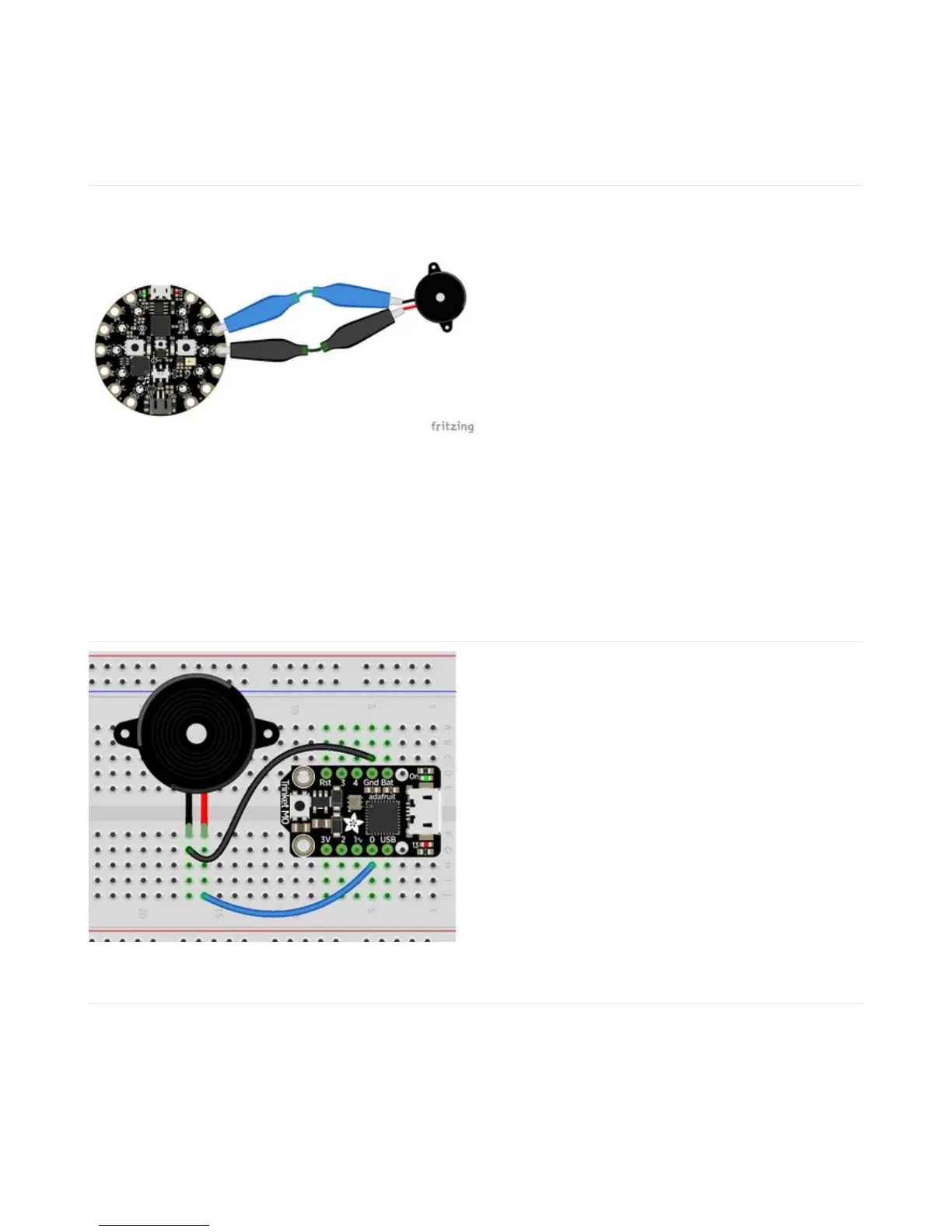
Trinket M0
Note: A2 on Trinket is also labeled Digital "0"!
Use jumper wires to connect GND and D0 to different
legs of the piezo.
Trinket has PWM available on the following pins: D0, A2,
SDA, D2, A1, SCL, MISO, D4, A4, TX, MOSI, D3, A3, RX,
SCK, D13, APA102_MOSI, APA102_SCK.
There is NO PWM on: A0, D1.
 Loading...