2-2
12704A Resistivity Chamber Operation Manual
2.1 Rear Panel
2. Part Descriptions
2.1 Rear Panel
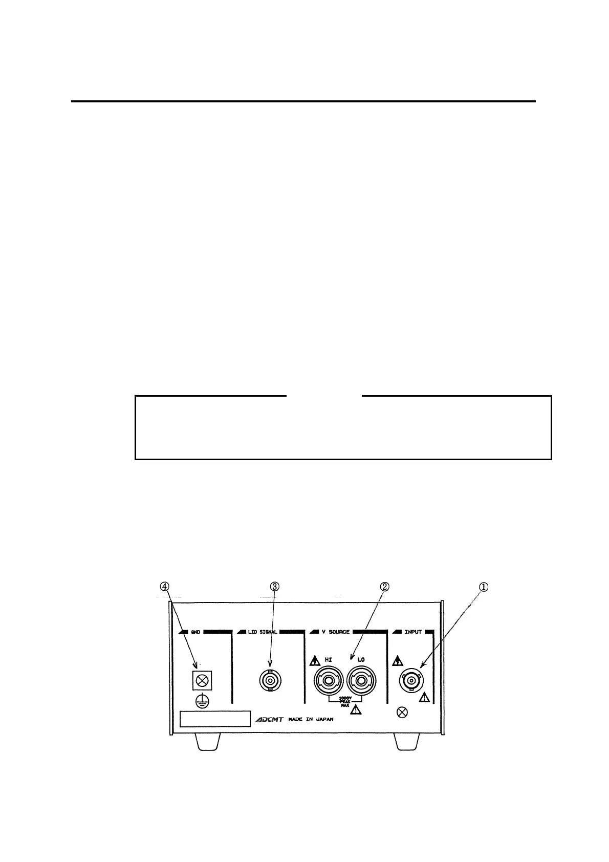
See Figure 2-1 "Rear Panel."
1. INPUT connector
A connector to connect with a measuring instrument having a triaxial connector on the
INPUT such as the 8340A, 8240, 8252 or 5450/5451.
The center contact is connected to the main electrode.
2. V SOURCE terminal
A connector to connect with the voltage output terminal of the 8340A, 8252 or 5450/5451.
While the HI connection is switched between the guard electrode and the opposed elec-
trode by the RESISTIVITY switch, the LO is always connected to the chassis. The HI
connection is disconnected when the cover is opened, and is connected to the guard elec-
trode or opposed electrode when it is closed.
If a cable is disconnected with voltage being applied from a voltage source, voltage
generation will occur on the end of the cable. Be sure to set the voltage OFF or
STANDBY before disconnecting the cable.
3. LID SIGNAL connector
Outputs an opening/closing signal of the cover. When the cover is closed, the terminals are
short-circuited. When it is closed, the terminals are open-circuited.
4. GND terminal
A grounding terminal. It is connected to the chassis of the 12704A.
Ground this terminal for electric shock prevention.
Figure 2-1 Rear Panel
WARNING