3-3
12704A Resistivity Chamber Operation Manual
3.1.1 Connecting with the 8340A
3.1.1 Connecting with the 8340A
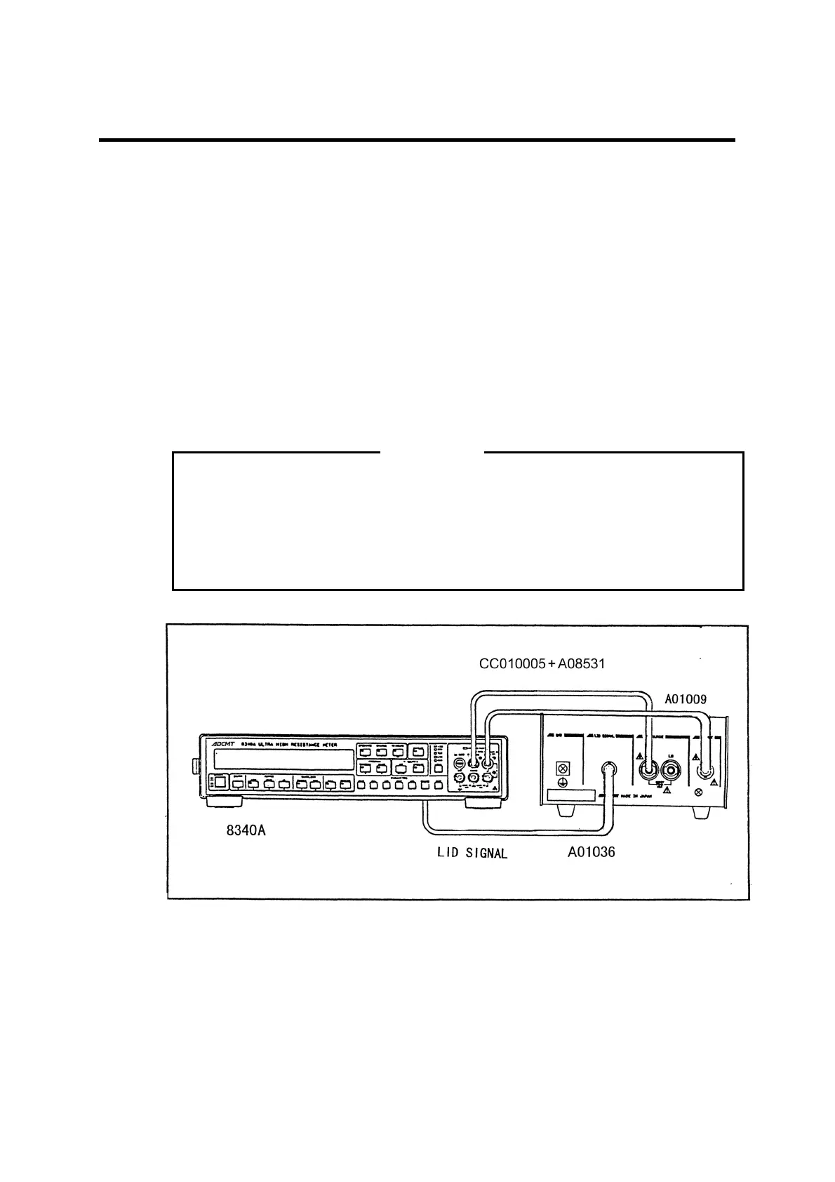
See Figure 3-1.
(1) Connect the INPUT terminal of the 8340A to the INPUT terminal of the 12704A by us-
ing the TRIAX-TRIAX cable (A01009).
(2) Connect the V SOURCE terminal of the 8340A to the V SOURCE HI terminal of the
12704A by using the output cable (CC010005) and the banana adapter (A08531).
(3) When using the LID SIGNAL function of the 12704A, connect the LID SIGNAL IN-
PUT on the rear panel of the 8340A to the LID SIGNAL connector of the 12704A by
using the BNC-BNC cable (A01036).
(4) Fix the short bar of the 8340A between the GND, GUARD and LO terminals.
The 8340A outputs applied voltage of maximum 1000 V. Perform measurement with
great care.
If a cable is disconnected with voltage being applied from the V SOURCE, voltage
generation will occur on the end of the cable. Be sure to set the voltage STANDBY
before disconnecting the cable.
Figure 3-1 Connecting with the 8340A
WARNING