3-5
12704A Resistivity Chamber Operation Manual
3.1.4 Connecting with the 5450/5451
3.1.4 Connecting with the 5450/5451
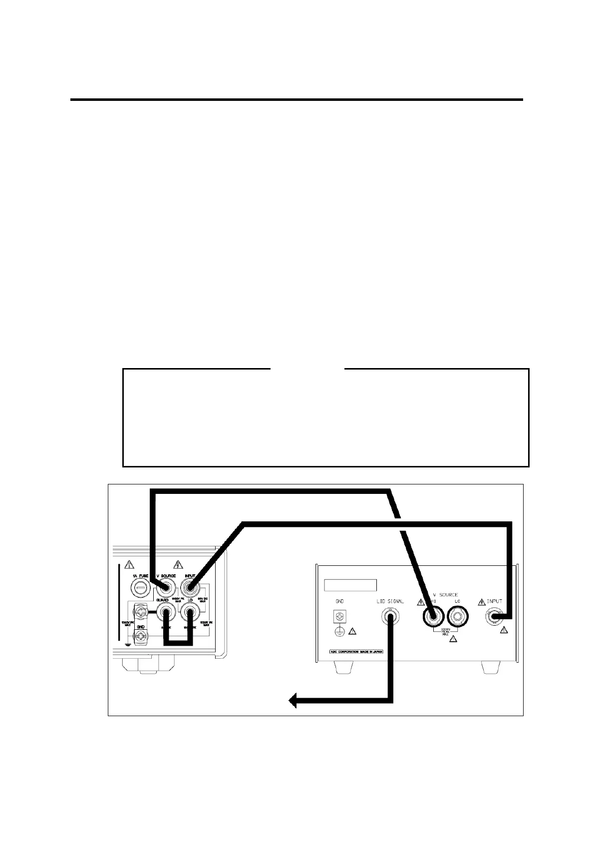
See Figure 3-2.
(1) Connect the INPUT terminal of the 5450/5451 to the INPUT terminal of the 12704A by
using the S.TRIAX-TRIAX cable (CC010004/CC015003+A01009) for the 5450 or the
TRIAX-TRIAX cable (A01009) for the 5451.
(2) Connect the V SOURCE terminal of the 5450/5451 to the V SOURCE HI terminal of
the 12704A by using the output cable (CC010005).
(3) When using the LID SIGNAL function of the 12704A, connect the INTERLOCK/LID
on the rear panel of the 5450/5451 to the LID SIGNAL connector of the 12704A by us-
ing the BNC-BNC cable (A01036). The INTERLOCK/LID function of the 5450/5451
operates differently depending on the setting. For more information on the function and
its setting method, refer to the 5450/5451 Operation Manual.
(4) Fix the short bar of the 5450/5451 between the LO and GUARD terminals.
The 5450/5451 outputs applied voltage of maximum 1000 V. Perform measurement
with great care.
If a cable is disconnected with voltage being applied from the V SOURCE, voltage
generation will occur on the end of the cable. Be sure to set the voltage STANDBY
before disconnecting the cable.
12704A
CC010005
A140001
5450: CC01 00 04 / CC015003 + A01009
5451: A01009
5450/5451
To INTERLOCK/LID terminal
on t he rear pan el
A01036
Figure 3-2 Connecting with the 5450/5451
WARNING