Page 43 of 84
66
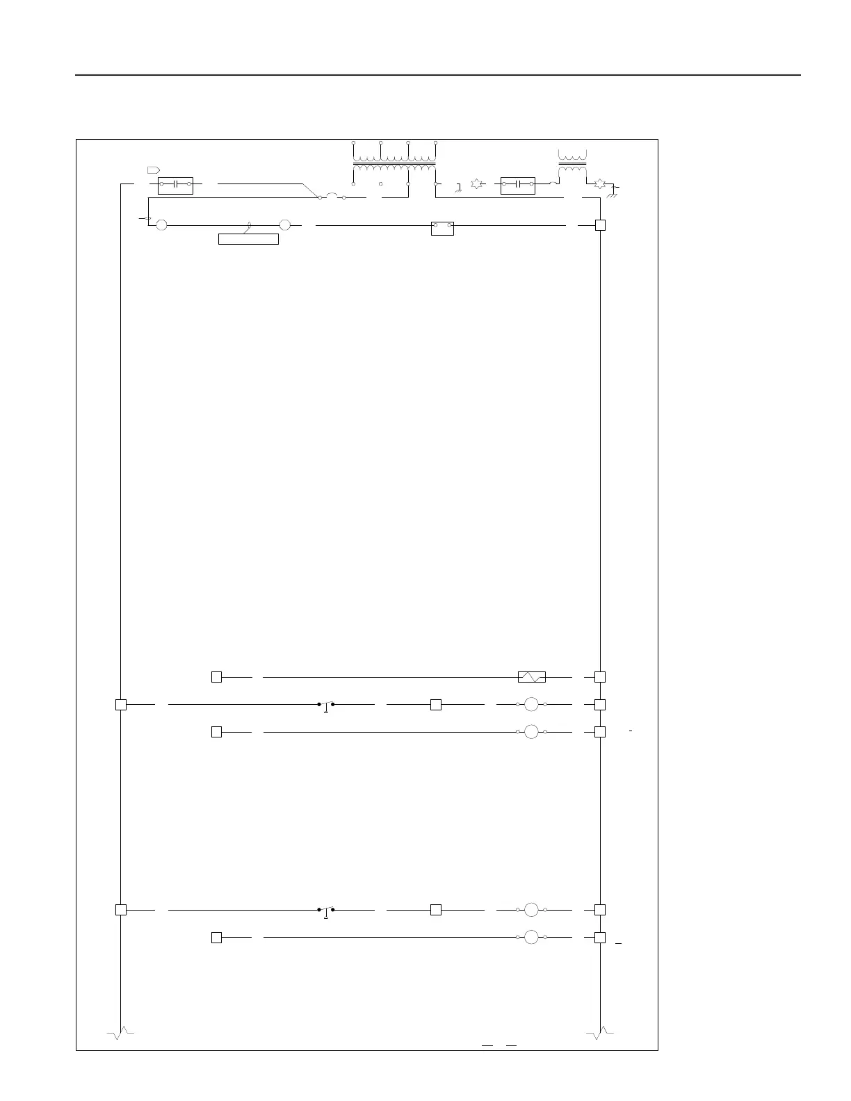
WIRINGDIAGRAM#PrelimWD|PROA180B2A3DEBDBB2B|230‐3‐60|SHEET2OF7|12/10/19DWNCHK.
67
68
69
70
71
72
73
74
75
76
77
78
79
80
81
82
83
84
85
86
87
88
89
90
91
92
93
94
95
96
97
98
99
100
101
102
103
104
105
106
107
108
109
110
111
112
113
114
115
116
117
118
119
120
121
122
123
124
125
126
127
128
129
130
UNLOADER
SOLENOID#1
TB1
HP2
HP1
TB1
TB1
CC2
CC1EnableCompressor#1
EnableCompressor#2
Y1
Y2 O
C
C
BL
BL
A2A1
A2A1
CONTINUEDONSHEET3
1,2,3,4,
10
Y
11,12,13,
14,9
HP1
R R HPR1
1413
BL CY 351
HP2
R R HPR2
1413
BL CO 345
TB1
HP1
TB1
HP2
Y
O
CBL
TB1
EnableUnloader#1 U1 PR
T3
96VA
CLASS2
50/60HZ
24V
TB4
G‐14
Line
Voltage
TB4
K3 K4
NOTE:SEE“T3”ONSHEET1
FORWIRINGCONTINUATION
PMAUX
NO
C
R
PM
NOTE:SEE“T1”ONSHEET1
FORWIRINGCONTINUATION
T1
50/60HZ
0V
208V
230V
460V
115V
24V
0V
X3X2XFX1
G‐14
R‐14
R‐14R‐14
BL‐14
CB
TB2 TB2
PM
8 1
7
7 6
Removejumperwhen field
installedsafetiesareused
R‐14
CBK
BL
J2J1
Y
O
Figure 17b: Typical Electrical Wiring Diagram
PR Series Installation, Operation, and Maintenance Manual