Page 48 of 84
391
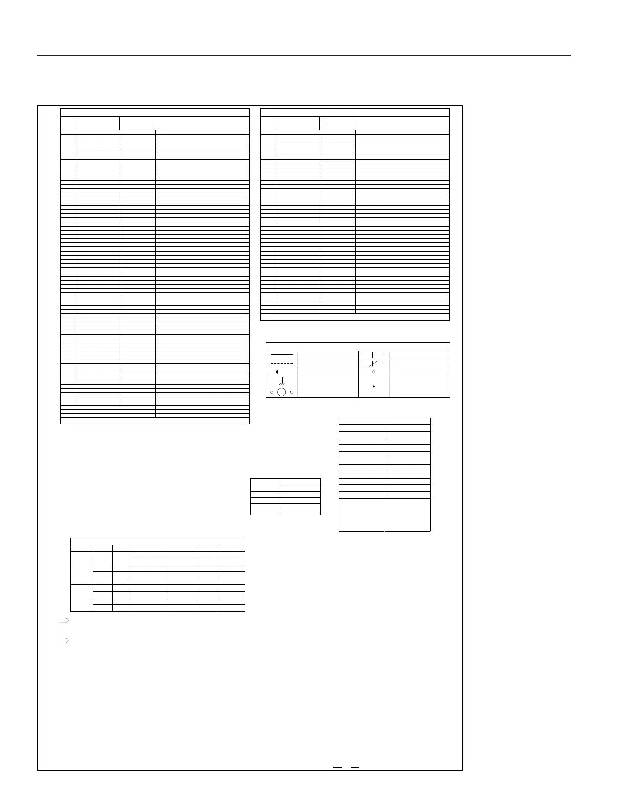
WIRINGDIAGRAM#PrelimWD|PROA180B2A3DEBDBB2B|230‐3‐60|SHEET7OF7|12/10/19DWNCHK.
392
393
394
395
396
397
398
399
400
401
402
403
404
405
406
407
408
409
410
411
412
413
414
415
416
417
418
419
420
421
422
423
424
425
426
427
428
429
430
431
432
433
434
435
436
437
438
439
440
441
442
443
444
445
446
447
448
449
450
451
452
453
454
455
FIELDPOWERSUPPLY208/230/460/575‐3‐60.MINIMUMCIRCUITAMPACITYAND
MAXIMUMSIZEANDTYPEOFBRANCH‐CIRCUITSHORT‐CIRCUITANDGROUND‐FAULT
PROTECTIONPERUNITRATINGPLATE.PROVIDEDISCONNECTINGMEANSASREQUIRED.
TYPICALMOTORSANDCOMPRESSORSSHOWN.SEECONNECTIONDIAGRAMONMOTOR
ORCOMPRESSORFORACTUALWIRINGDETAIL.
FUSENO. CLASS VAC AMPS‐208/230V AMPS‐460V XFMR TIMEDELAY
CC 600 3 2 350VA YES
CC 600 2 1.5 250VA YES
CC 600 2 1.5 200VA YES
CC 600 1.5 3/4 150VA YES
F2,F9,F10 CC 600 1 1 N/A YES
CC 600 16 16 350VA YES
CC 600 10 10 250VA YES
CC 600 10 10 200VA YES
CC 600 6 6 150VA YES
CB
FUSETABLE
F1,F3
2
1
ABBREVIATION COLOR
BK BLACK
BL BLUE
BR BROWN
G GREEN
O ORANGE
PK PINK
PR PURPLE
R RED
W WHITE
Y YELLOW
WIRECOLORLEGEND
NOTE:NUM BERPLACEDAFTERDASH
FOL L OWINGCOLORCODE INDICATESWIRE
GAGE.EX.‐BK‐12ISABLACK,12AWGWIRE.
NONUMBERAFTERCOL ORCODEINDICATES18
AWGWIRE.EX.‐BKISABLACK18AWGWIRE.
WireSize M axiumRun
18AWG 50Feet
16AWG 75Feet
14AWG 100/125Feet
14AWG 150/200Feet
24VoltClass2MinimumWireSize
ITEM
FUNCTIONAL
DESIGNATION
LINENUMBER DESCRIPTION
101 SFC 148 Su
l
FanMotorContactor
101 SFR 148 Su
l
FanMotorRela
102 MSP‐SF 38 MotorStarterProtection‐Su
l
Fan
1 03 SF‐VFD 38 Su
l
Fan‐VariableFre
uenc
Drive
104 CC1 110 Com
ressorContactorno.1
104 CC1A
CC1B 110
113 Com
ressorContactorno.1Aand1B
105 CC1‐A1
CC1‐A2 # "CC1"Auxiliar
Contactno.1and2
105 CC1A‐A1
CC1A‐A2 # "CC1A"Auxiliar
Contactno.1and2
106 CC1B‐A1 # "CC1B"Auxiliar
Contactno.1
1 07 MSP‐CC1 1 MotorStarterProtection‐“CC1”
107 MSP ‐CC1A
MSP‐CC1B 1
6 MotorStarterProtection‐“CC1A
CC1B”
108 CC2 123 Com
ressorContactorno.2
108 CC2A
CC2B 123
126 Com
ressorContactorno.2Aand2B
109 CC2‐A1
CC2‐A2 # "CC2"Auxiliar
Contactno.1and2
109 CC2A‐A1
CC2A‐A2 # "CC2A"Auxiliar
Contactno.1and2
110 CC2B‐A1 # "CC2B"Auxiliar
Contactno.1
1 11 MSP‐CC2 11 MotorStarterProtection‐“CC2”
111 MSP ‐CC2A
MSP‐CC2B 11
16 MotorStarterProtection‐“CC2A
CC2B”
112 DIG1 108 Di
ital Com
ressorno.1Unloade rSolenoid
112 DIG1
DIG2 108
121 Di
ital Com
ressorno.1and2UnloaderSolenoid
113 DR1 91 DefrostRela
no.1
113 DR1
DR2 91
99 DefrostRela
no.1and2
114 DTM1 88 DefrostTime rno.1
114 DTM 1
DTM2 88
96 DefrostTimerno.1and2
115 EFC 152 ExhaustFanContactor
115 EFR 152 ExhaustFanRela
116 MSP‐EF 46 MotorStarterProtection‐ExhaustFan
117 EFVFD 46 ExhaustFan‐Variabl e Fre
uenc
Drive
118 EGB 4 E
ui
mentGroundin
Bar
119 F1
F2
F3 59
60
61 Fusin
‐SeeFuseTabl e onthissheet
120 CB 71 CircuitBreaker‐See FuseTableonthissheet
121 OFC1 79 OutdoorFanContactorno.1
121 OFC1
OFC2 79
83 OutdoorFanContactorno.1and2
1 21 MSP‐OFVFD1&2 17
29 MSP.OutdoorFanVFDno.1and2
1 22 MSP‐OF1 22 MotorStarterProtection‐OutdoorFanno.1
1 23 MSP‐OF2 30 MotorStarterProtection‐OutdoorFanno.2
1 23 MSP‐OF2 26 MotorStarterProtection‐OutdoorFanno.2
1 24 MSP‐OF3 30 MotorStarterProtection‐OutdoorFanno.3
1 25 MSP‐OF4 34 MotorStarterProtection‐OutdoorFanno.4
126 OF1VFD 22
25 OutdoorFanVariable Fre
uenc
Driveno.1
126 OF1VFD
OF2VFD 22
25
30 OutdoorFanVariableFre
uenc
Driveno.1and2
128 HARM Sheet4 Heatin
Analo
Rela
Module
129 MDC1 214 Modulatin
Dischar
e‐LineControllerno.1
129 MDC1
MDC2 214 Modulatin
Dischar
e‐LineControllerno.1and2
130 MRC1 202 Modulatin
ReheatControllerno.1
130 MRC1
MRC2 202 Modulatin
ReheatControllerno.1and2
131 PDB 1
2
3 PowerDistributionBlock
132 PM 59
71 Power
PhaseMonitor
133 RHR 156 ReheatRela
134 RVR 158 Reversin
Valve Rela
135 T1 62
67 ControlTransformerno.1
136 T2 200 ControlTransformerno.2
137 TB1 Sheet2‐5 Terminal Boardno.1
138 TB2 71 Te rminal Boardno.2
139 TB3 204
21 6 Te rminalBoardno.3
140 TB‐A Sheet5 Te rminalBoardno.‐A
144 TD1 113 TimeDela
no.1
144 TD1
TD2 113
126 TimeDela
no.1and2
145 BY‐PASSTIMER1 115 B
‐
assTimeDela
no.1
145 BY‐PASSTIM ER1&2 115
128 B
‐
assTimeDela
no.1and2
146 WMC 463 WheelMotorContactor
146 WMR ??? WheelMotorRela
1 47 MSP‐WM 54 MotorStarterProtection‐WheelMotor
148 WMVFD 54 WheelMotorVariableFre
uenc
Drive
149 C450 460 JohnsonControlC450
0‐10VDC
150 WM‐CS 55
329 WheelMotorCurrentSensor
151 1KOhm 212
213 Resistor
1KOhmsforMDC
152 CR1 112 Com
ressorRela
no.1
152 CR1andCR2 112
125 Com
ressorRela
no.1and2
LEGEND‐ITEMSINSIDECONTROLPANEL
#SEELINENUMBERTOTHERIGHTOFCONTA CTORCOILONWIRINGDIAGRAM.
ITEM
FUNCTIONAL
DESIGNATION
LINENUMBER DESCRIPTION
101 APS 265 AirPre ssure Switch
Su
l
Fan
102 APS 265
266 AirPressureSwitch
Su
l
FanandExhaustFan
103 BCTL 165 BCTL
104 BOS1 132 Bleed‐OffSolenoidno.1
105 BOS1
BOS2 132
134 Bleed‐OffSolenoidno.1and2
106 CCH1 4 Com
ressorCrankcaseHeaterNo.1
107 CCH1A
CCH1B 4
9 Com
ressorCrankcaseHeaterNo.1Aand1B
108 CCH2 14 Com
ressorCrankcaseHeaterNo.2
109 CCH2A
CCH2B 14
19 Com
ressorCrankcaseHeaterNo.2Aand2B
110 CM1 2 Com
ressorMotorNo.1
111 CM1A
CM1B 2
7 Com
ressorMotorNo.1Aand1B
112 CM2 12 Com
ressorMotorNo.2
113 CM2A
CM2B 12
17 Com
ressorMotorNo.2Aand2B
114 COPM1 110
181 Com
ressorOvercu rrentProtectionModuleno.1
115 COPM2 123
183 Com
ressorOvercu rrentProtectionModuleno.2
116 DPT260 340 DifferentialPressureTransmitter260
SF
117 DPT260 340
34 2 Differen t i al Pre ssureTransmitter260
SFand EF
118 DTT1 93 DefrostT’statNo.1
119 DTT1
DTT2 93
101 DefrostT’statNo.1and2
120 ECDA 179 EconomizerDam
erA c tuator
121 ECDA 178
179 EconomizerDam
erA c tuator
122 EFM1 47 Ex haustFanMotorNo.1
123 FS 71 FireStat
124 FZT 266 FreezeStat
125 HP1 110 Hi
hPressureSwitchNo.1
126 HP2 123 Hi
hPressureSwitchNo.2
127 LP1 265 LowPressureSwitchNo.1
128 LP2 266 LowPressureSwitchNo.2
1 29 LSS1A
LSS1B 136
138 Li
uidSub‐Coolin
Solenoidno.1Aand1B
1 30 LSS2A
LSS2B 140
142 Li
uidSub‐Coolin
Solenoidno.2Aand2B
131 LLS1 144 Li
uidLineSolenoidno.1
132 LLS1
LLS2 144
146 Li
uidLineSolenoidno.1and2
133 OFM1 23 OutdoorFanMotorNo.1
134 OFM2 31 OutdoorFanMotorNo.2
135 OFM2 27 OutdoorFanMotorNo.2
136 OFM3 31 OutdoorFanMotorNo.3
137 OFM4 35 OutdoorFanMotorNo.4
138 OFM5 39 OutdoorFanMotorNo.5
139 OFM6 43 OutdoorFanMotorNo.6
140 RVS1 73 Reversin
Valve No.1
1 41 RVS1
RVS2 73
76 Reversin
Valve No.1and2
1 42 SF M1 39 Su
l
FanMotorNo.1
143 WFS 268 WaterFlowSwitch
144 WM 55 ECWheelMotor
LEGEND‐ITEMSOUTSIDECONTROL PANEL
#SEELINENUMBERTOTHERIGHTOFCONTA CTORCOILONWIRINGDIAGRAM.
FA CTORYWIRING NORMALLYOPENCONTACTS
FIELDWIRING NORMALLYCLOSEDCONTA C TS
EARTHGROUND IDENTIFIABL ETERMINAL
CHASSIS(PANEL )GROUND
COIL
SYMBOLLEGEND
NON‐IDENTIFIABLETERMINAL,
OTHERWIREJUNCTIONS,
INCLUDINGSCHEM A TIC
Figure 17g: Typical Electrical Wiring Diagram
PR Series Installation, Operation, and Maintenance Manual