IRIS-4 Technical Reference Manual.docx 12/01/2023 page 15
4.2.1.1 Expansion boards
An expansion board can be fitted to the main terminal to provide additional functionality.
4.2.1.1.1 Pin Inputs
The EXT1 expansion board provides 12 additional pin inputs
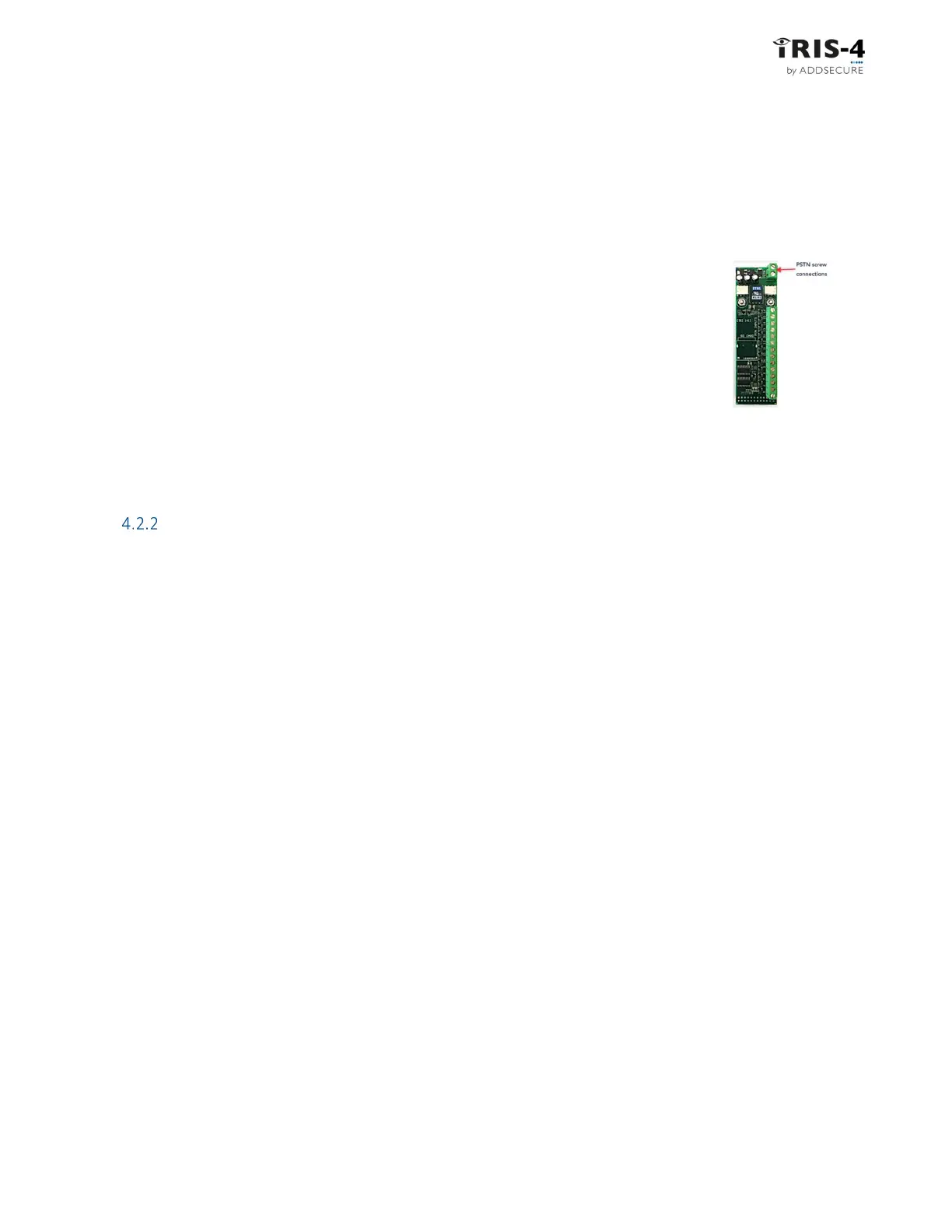
4.2.1.1.2 PSTN and input pins
The EXT2 expansion board provides 12 additional pin inputs and a PSTN Dial-out
for a PSTN connection via the 2-screw terminal block (see Figure 4).
Connect the PSTN line to the PSTN screw terminals, which are not polarity
sensitive.
4.2.1.1.3 Relays and input pins
The EXT3 expansion board provides 12 additional pin inputs and 3 mechanical relay outputs. This board is
not supported on the 4xxG.
Mount the terminal
4.2.2.1 Mounting the 160
Choose a suitable location, considering the routing of both power and terminal interface cables. Follow this
procedure:
1 Remove the cover by removing the two screws accessible through the cover.
2 Once released, lift the lid slightly and push until lid comes off.
3 Remove the terminal PCB (retained by two clips to left and right off the board).
4 Position the housing on the wall and drill three holes.
5 Feed the cables through the opening at the base of the plate, or via the ‘knock-outs’, and secure
the plate to the wall with the three screws supplied.
6 Slide the PCB back into the top retainers and within the side pillar and then gently secure the
terminal back in place using the release clips.
7 Continue with installation and configuration of the terminal.
8 When finished, re-attach the cover with the two screws. This also affixes the PCB in place.
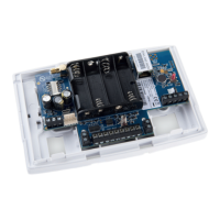
4.2.2.2 Mounting the 2xx
Choose a suitable location, considering the routing of cables
for both power and
the
panel
terminal
interface. Remove the
two case fixing screws under the slide cover and open the unit.
Now release the two
clips on the base holding the PCB in place.
Position the housing on the wall and drill three holes. Feed the cables through the opening at the base of the
plate, or via the
'knock-outs’, and secure the plate to the wall with the three screws supplied.
Continue with installation and configuration of the terminal.
When finished, re-attach the cover with the two screws and re-position the slide cover.
Figure 4