– 18 –
SYSTEM INSTALLATION NOTES
General Information
• Touchpads must be set for addresses 16-23 (first touchpad is address 16, which is different from previous
controls) and programmed in data fields *190-*196.
• Zone Expander Modules must be set for specific addresses (07-11), based on the zone numbers used (see table
of addresses in Installation and Setup Guide, K5305V3).
• 4204 Relay Modules must be set for specific addresses (12-15).
For Canadian Installations:
• All devices and accessories used in a Canadian installation must be Listed for use in Canada.
• Wiring is to be in accordance with the Canadian Electric Code, Part I, the Standard for Installation and
Classification of Burglar Alarm Systems for Financial and Commercial Premises, Safes, and Vaults,
CAN/ULC-S302, and the Standard for the Installation of Residential Fire Warning Systems, CAN/ULC-S540.
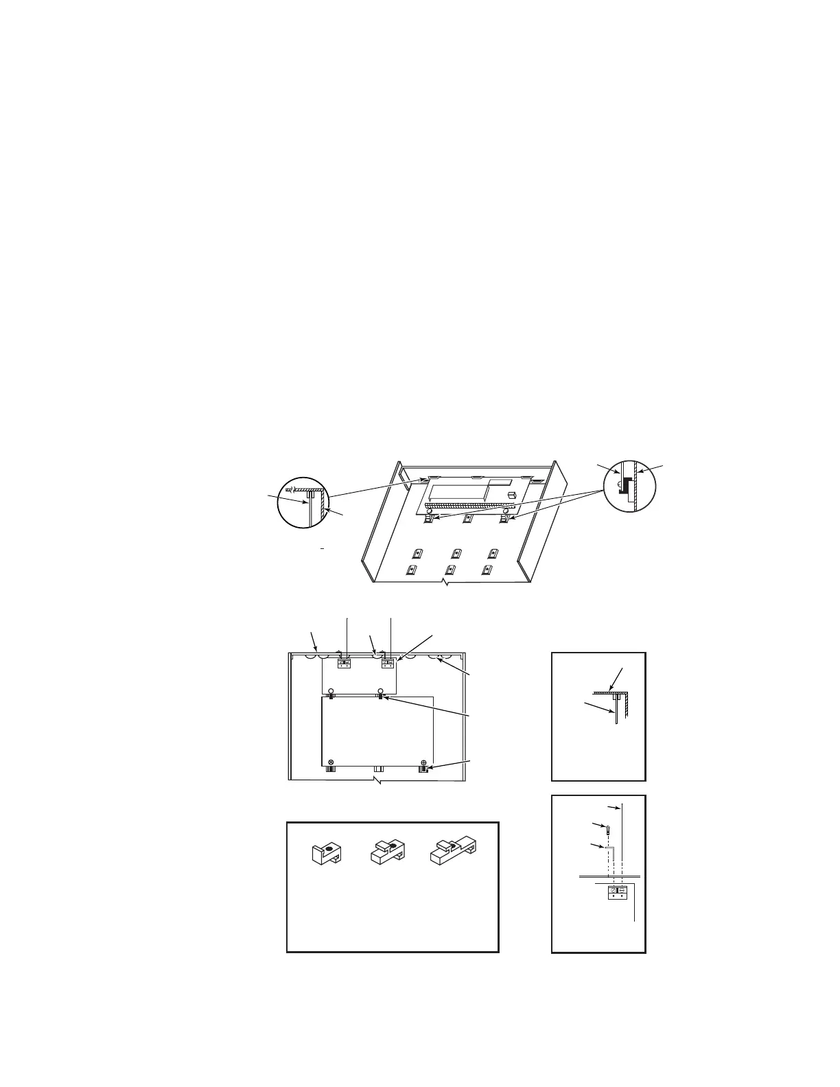
Mounting
1. Hang two short mounting clips (provided) on the raised cabinet tabs (see Detail B in Fig. 2).
2. a. Insert the top of the circuit board into the slots at the top of the cabinet. Make sure that the board
rests on the correct row (see Detail A).
b. Swing the base of the board into the mounting clips and secure the board to the cabinet with the
accompanying screws (see Detail B).
Notes
• Before installing the cabinet's contents, remove the metal cabinet knockouts required for wiring entry. Do not
remove the knockouts after the circuit board has been installed.
+
+
CIRCUIT
BOARD
DETAIL B
SIDE VIEW
OF MOUNTING
CLIPS
DETAIL A
SIDE VIEW
OF BOARD
SUPPORTING
SLOTS
CIRCUIT
BOARD
ADT3000-013-V0
CABINET
CABINET
Mounting the PC Board
ANTENNA
MOUNT
(2 PLACES)
ANTENNA
(2)
SCREW
(2)
BLACK
MOUNTING
CLIP
RED
MOUNTING
CLIP
WHITE
MOUNTING
CLIP
GROUNDING
LUG
(2)
NOTE
A COMBINATION OF THESE MOUNTING CLIPS HAS BEEN
INCLUDED IN YOUR INSTALLATION KIT.
USE THE APPROPRIATE CLIPS FOR MOUNTING.
IF NO RF RECEIVER IS USED, MOUNT THE PC BOARD USING
EITHER THE WHITE OR BLACK CLIPS, WHICHEVER ARE
INCLUDED IN THE CONTROL PANEL'S HARDWARE KIT.
DETAIL A
SIDE VIEW
OF BOARD -
SUPPORTING SLOTS
CIRCUIT
BOARD
CABINET
MOUNTING
CLIP
CABINET
MOUNTING
CLIP
CONTROL
CIRCUIT
BOARD
BOARD
SUPPORTING
SLOTS
RECEIVER CIRCUIT BOARD
++
A B
pc_mount-001-V1
DETAIL B
ANTENNA AND GROUNDING
LUG INSTALLATION
INSTALLATION WITH RECEIVER CIRCUIT BOARD
Mounting the PC Board and RF Receiver