NetVanta 4300/4400 Series Physical Descriptions
61200890E2-34T Copyright © 2019 ADTRAN, Inc. 15
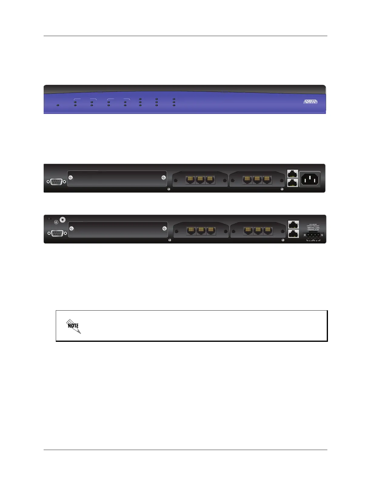
NetVanta 4305 Front Panel Design
The NetVanta 4305 front panel is shown below. Front panel LED descriptions are given in Table 1 on page
20.
STATUS
NET 2
WAN
DBU
TD
RD
TD
RD
LNK
LAN 2
STATUS
ACTIVITY
TEST
WIDE SLOT 1
TD
RD
LNK
LAN 1
NET 1
WAN
DBU
TD
RD
NetVanta 4305
Figure 1. NetVanta 4305 Front Panel Layout
NetVanta 4305 Rear Panel Design
Figure 2 shows the NetVanta 4305 (AC) rear panel and Figure 3 shows the NetVanta 4305 (DC) rear panel.
The chassis are shown with the T1/FT1 + DSX-1 NIM installed.
SLOT 1 NET/DBU
CONSOLE
SLOT 2 NET/DBUSLOT 3 WIDE MODULE
ETH 0/1
ETH 0/2
100-250VAC
50/60Hz
WAN-T1 DSX-1 DBUWAN-T1 DSX-1 DBU
Figure 2. NetVanta 4305 (AC version) Rear Panel Layout
SLOT 1 NET/DBU
CONSOLE
SLOT 2 NET/DBUSLOT 3 WIDE MODULE
ETH 0/1
ETH 0/2
WAN-T1 DSX-1 DBUWAN-T1 DSX-1 DBU
Figure 3. NetVanta 4305 (DC version) Rear Panel Layout
Rear Panel Interfaces and LEDs
CONSOLE Interface
The CONSOLE interface is an EIA-232 serial port (DCE), which provides for local management and
configuration (via a DB-9 female connector). Table A-4 on page 57 shows the
CONSOLE port pinouts.
NET/DBU and Wide Module Option Slots
The SLOT 3 WIDE MODULE slot accepts the Octal T1/E1 Wide Module. The SLOT 2 NET/DBU and
SLOT 1 NET/DBU option slots support various NIM plug-in modules. These option modules are
described in the section Option Modules on page 21.
Connection directly to an external modem requires a cross-over cable.
 Loading...