61200990L1-34N Copyright © 2010 ADTRAN, Inc. 33
APPENDIX A. PIN ASSIGNMENTS
The following tables provide the pin assignments for the NetVanta 5305 System controller and option
modules.
Controller Module Pinouts
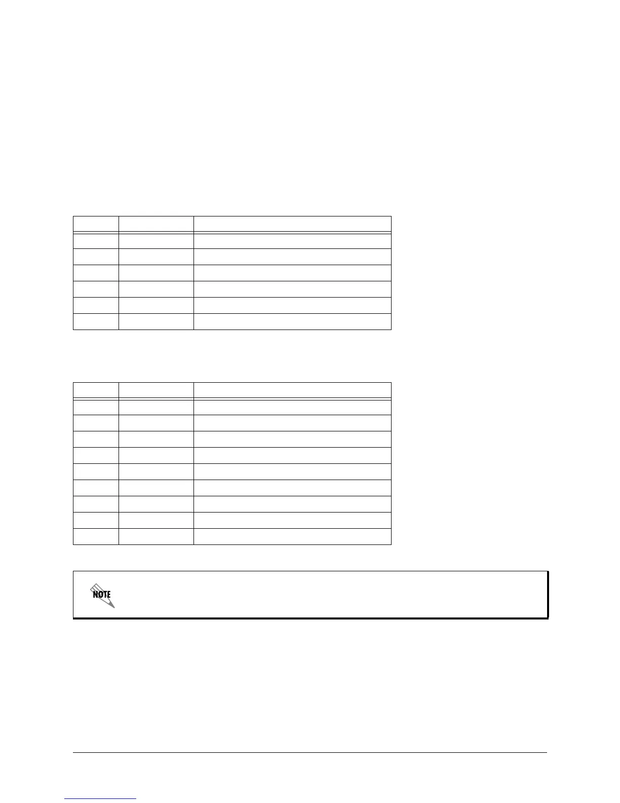
Table A-1. 10/100Base-T Ethernet Port Pinouts
Pin Name Description
1 TX1 Transmit Positive
2 TX2 Transmit Negative
3 RX1 Receive Positive
4, 5 — Unused
6 RX2 Receive Negative
7, 8 — Unused
Table A-2. CONSOLE Port (DCE) Pinouts
Pin Name Description
1 DCD Data Carrier Detect (output)
2 RD Receive Data (output)
3 TD Transmit Data (input)
4 DTR Data Terminal Ready (input)
5 SG Signal Ground
6 DSR Data Set Ready (output)
7 RTS Request to Send - flow control (input)
8 CTS Clear to Send (output)
9 RI Ring Indicate (output)
Connection directly to an external modem requires a crossover cable.
 Loading...