NetVanta 5305 Hardware Installation Guide Product Overview
61200990L1-34N Copyright © 2010 ADTRAN, Inc. 19
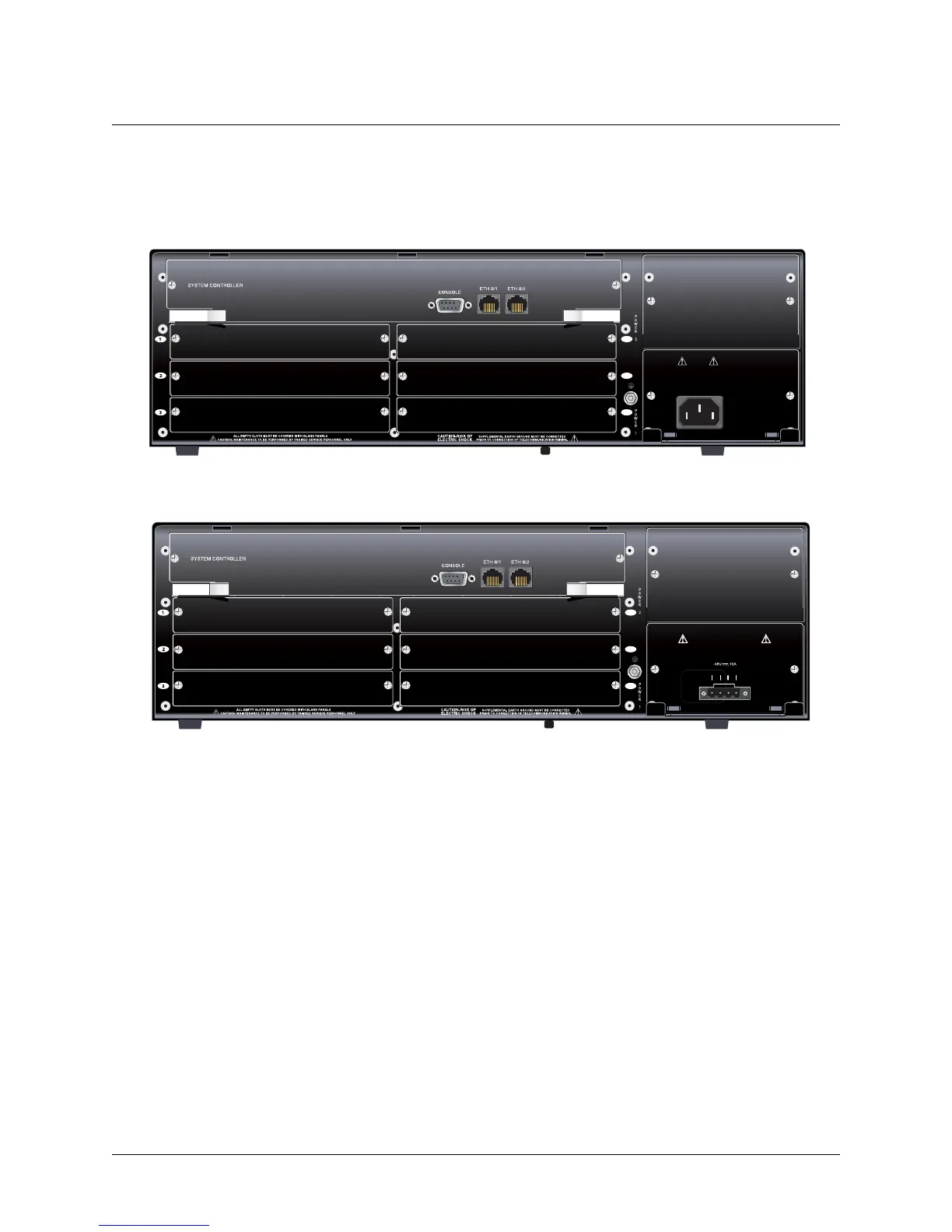
Reviewing the Rear Panel Design
Figure 2 on page 19 shows the NetVanta 5305 AC rear panel layout, and Figure 3 on page 19 shows the
NetVanta 5305 DC rear panel layout. Pinouts for the connectors are given in Appendix A on page 33.
Figure 2. NetVanta 5305 AC Rear Panel Layout
Figure 3. NetVanta 5305 DC Rear Panel Layout
Rear Panel Interfaces
CONSOLE Port
The CONSOLE port, a DB-9 interface located on the rear panel, connects to a computer or modem and
provides the following functions:
• Accepts electrical EIA-232 input from a PC or modem for controlling the NetVanta 5305.
• Operates at rates ranging from 9.6 kbps to 115.2 kbps.
• Acts an input for either VT100 or PC control.
1
2
3
REMOVE POWER CORD PRIOR
TO REMOVAL OF POWER SUPPLY
CAUTION:
85-130VAC/190-250VAC
4A/2A 50/60Hz
6
5
4
1
2
3
6
5
4
CAUTION REMOVE POWER CORD PRIOR
TO REMOVAL OF POWER SUPPLY
USE COPPER
CONDUCTORS ONLY
AB
RET -48V RET -48V
 Loading...