ELECTRICAL INSTALLATION
POWER SWITCH LOCATION:
The gate operator uses a built-in power switch to control power to the operator and controller. This switch should be turned
OFF during installation and service. Failure to use this switch can result in unexpected gate movement. Please note:
1. The switch is located on the LEFT side of the control box.
2. DOWN position = OFF. UP position = ON.
3. This switch must be used to turn OFF AC and battery power. Only disconnecting AC power still allows battery power to the
operator, controller, and accessories.
4. Turn OFF until the installation is complete.
AC POWER GUIDELINES:
Under normal conditions, the gate operator will use a single phase AC power line to operate the gate, charge the batteries, and
power gate accessories. Use the following guidelines when installing the AC power:
1. Check the local wiring codes in all cases and follow all local building codes. Wiring and hookup should be performed by a qualified
electrician/installer only.
2. AC power should be supplied from a circuit breaker panel and must have its own dedicated circuit breaker. This supply must include
a green ground conductor.
3. Only use U.L. approved 14 AWG or larger 600 Volt Insulated Wire. Use the following chart to determine the AC wire size. This
information is for suggested use only - Check your local codes before installation.
4. Properly ground the gate operator to minimize or prevent damage from power surges and/or lightning. Use a grounding rod if
necessary. A surge suppresser is recommended for additional protection.
AC POWER CONNECTION:
To connect AC power to the gate operator:
1. Turn the circuit breaker for the AC gate operator power OFF before connecting the AC input wires.
2. Turn the Power Switch OFF located on the left side of the controller before connecting the AC input wires.
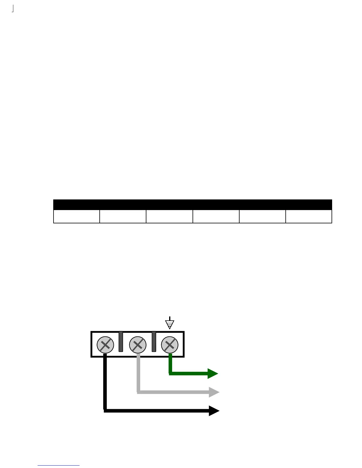
3. Connect the AC input wires to the AC terminal located on the bottom/center of the control box. See diagram below.
4. Batteries must be installed after the AC power is on. See Battery Power Connection.
Wire Size: 14 Gauge 12 Gauge 10 Gauge 8 Gauge 4 Gauge
Distance: 250 Feet 400 Feet 650 Feet 1000 Feet 2000 Feet
L1 L2
GREEN = Ground
WHITE = Neutral
BLACK = 120 VAC