LOOPS & LOOP DETECTORS
PLUG-IN LOOP DETECTOR CONNECTIONS:
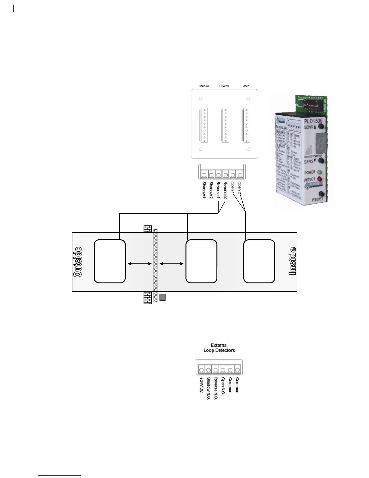
The gate operator may utilize PLD1500 Plug-in Loop Detectors to simplify installation, save space and eliminate extra wiring.
There are three plug-in terminals (Shadow, Reverse, Open) located on the gate controller. Detectors plugged into a specific
socket will perform that function. To connect a PLD1500:
EXTERNAL LOOP DETECTOR CONNECTIONS:
The gate operator may utilize external Loop Detectors. Refer to the manufacturer’s instructions for detailed wiring.
Plug-In Loop Detector Inputs:
1. Shadow Loop: Not used on DSL2000.
2. Reverse Loop: Plug detector into center socket. Make sure
detector is secure and snapped in.
3. Open Loop: Plug detector into left socket. Make sure detector
is secure and snapped in.
4. Set different frequencies for each loop detector.
5. Follow the directions provided with the PLD1500 for more
detailed settings.
Ground Loop Wire Connections:
1. Connect Reverse Loop wires to REVERSE 1 and REVERSE 2.
2. Connect Open Loop wires to OPEN 1 and OPEN 2.
Vehicular Gate Only
REVERSE
L
OOP
REVERSE
L
OOP
OPEN
L
OOP
4-5 Feet 4-5 Feet
External Loop Detector Inputs:
1. 24VDC is available to power external loop detectors. Connect
24VDC detector power to +24VDC and COMMON.
2. Shadow Loop: Not used on DSL2000.
3. Reverse Loop: Connect relay wires to REVERSE N.O. and
COMMON.
4. Open Loop: Connect relay wires to OPEN N.O. and COMMON.
5. Set different frequencies for each loop detector.
6. Follow the directions provided by the external loop detector
manufacturer for more detailed settings.