ACCESSORY CONNECTIONS
RADIO RECEIVER CONNECTIONS:
Radio Controls may be connected to the Radio Inputs to control the gate operator. When a Radio Control is active, the Radio
LED will light.
MAGLOCK & SOLENOID LOCK CONNECTIONS:
Magnetic and Solenoid Locks may be connected to the controller and utilize a 2 second delay on open to help dissipate
magnetic current or solenoid power for smoother openings.
Radio Input:
1. Allows Radio Controls to activate the gate and provides 24VDC.
2. NOTE: Wireless Edge Sensor Receivers should be connected
to the Edge Terminals. See page 19.
Connecting Radio Receivers:
1. Connect Radio Relay to RADIO N.O. and RADIO COMMON.
2. If the Radio Receiver uses 24VDC, connect Radio Power to
RADIO PWR +24VDC and RADIO PWR -24VDC.
3. Use the following chart for standard radio connections:
Radio
Receiver
AAA LiftMaster Linear Multi-Code
+24VDC
Red Red
N.O.
Gray Gray
Common
Gray Gray
-24VDC
Black Black
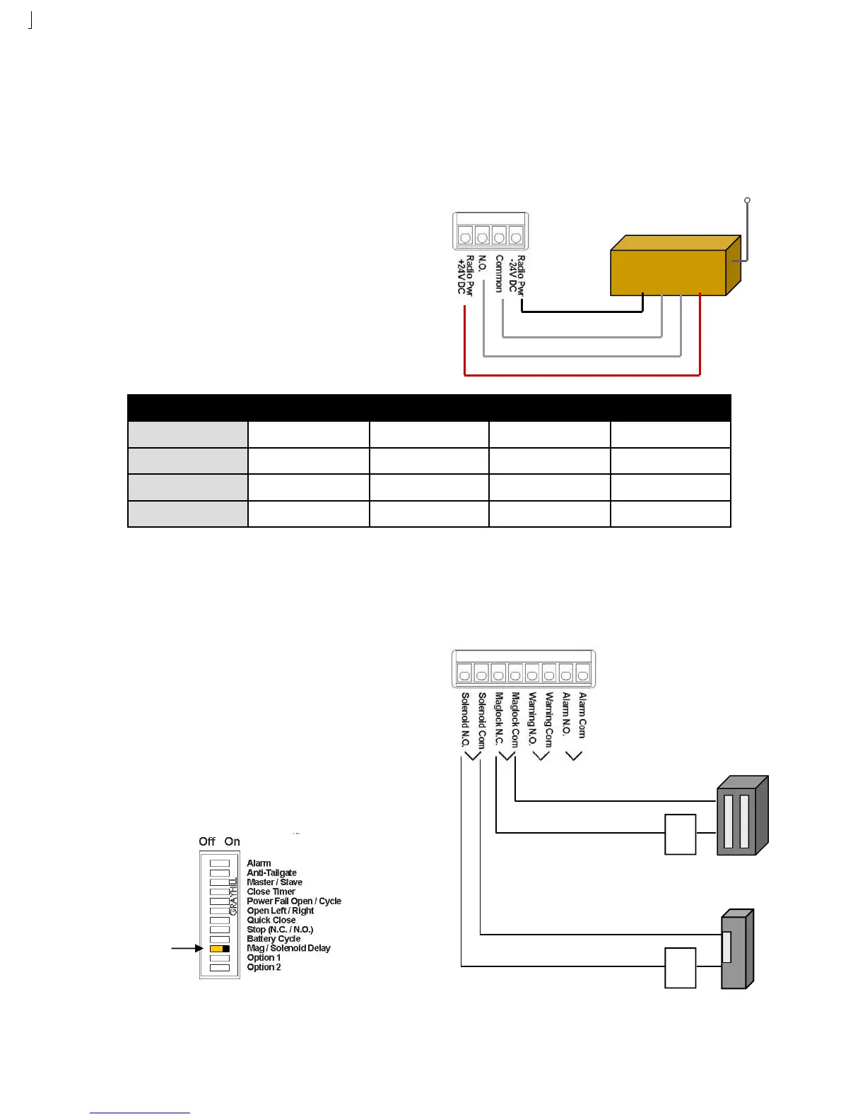
MagLock & Solenoid Inputs:
1. Allows Maglocks and Solenoid Locks to be connected to the
gate operator with a 2 second delay to open.
2. Maglocks use a NC relay contact. Solenoid Locks use a NO
contact.
Connecting Solenoid & Maglocks:
1. Set DIP Switch 10 to ON for a 2 second delay on open.
2. Connect Solenoids to SOLENOID NO and SOLENOID COM.
3. Connect Maglocks to MAGLOCK NC and MAGLOCK COM.
Switch 10:
ON
Solenoid
Lock
Power
Mag
Lock
Power