IMPORTANT SAFETY INFORMATION
INTERNAL ENTRAPMENT PREVENTION:
This vehicular gate operator is equipped with an inherent (Type A) entrapment sensing device. The system will sense an
obstruction in both the open and close cycles, and will reverse the direction of the gate travel upon encountering an
obstruction. If the system detects a second obstruction before reaching the full open or close limit after the initial reversal, a
warning alarm will activate and the operator will require a reset before resuming normal operation. This is called a “Hard
Shutdown”. Please read and follow the “Shutdown Conditions” section of this manual for more directions.
EXTERNAL ENTRAPMENT PREVENTION:
Non-contact and/or contact sensors must be installed to provide external entrapment prevention in accordance with UL325
section 3.1. Use only UL325 compliant devices and low voltage (24V) devices. Carefully follow the installation manual for the
UL325 device used for installation, usage, and maintenance.
Non-Contact Sensors (Photo Beams):
Non-contact sensors generally are photoelectric cells or like devices. For gate operators utilizing non-contact sensors:
1. Refer to the diagram below for placement of non-contact sensors.
2. Use care to reduce the risk of nuisance tripping, such as when a vehicle trips the sensor while the gate is still moving.
3. One or more non-contact sensors shall be located where a risk of entrapment or obstruction exists, such as the perimeter reachable
by a moving gate or barrier. Use caution when installing non-contact sensors since some devices only cover a select area. For
example, a photo beam will not cover the full height of a gate/fence area. Refer to the diagram below.
Contact Sensors (Edge Sensors):
Contact sensors generally are sensing edges or like devices. For gate operators utilizing contact sensors:
1. Refer to the diagram below for placement of contact sensors.
2. One or more contact sensors shall be located where the risk of entrapment or obstruction exists, such the leading edge, trailing
edge, and posts mounted inside and outside of the vehicular slide gate and motor.
3. Hardwired contact sensors shall be located and its wiring arranged so the communication between the sensor and the gate operator
is not subject to any mechanical damage.
4. Wireless contact sensors such as ones that transmit radio frequency (RF) signals to the gate operator for entrapment prevention
functions shall be located where the transmission of the signals are not obstructed or impeded by building structures, landscaping or
similar obstructions. All wireless contact sensors shall function under the intended end-use conditions.
Vehicular Gate Only
Pedestrian
Access
Fence
Fence Fence
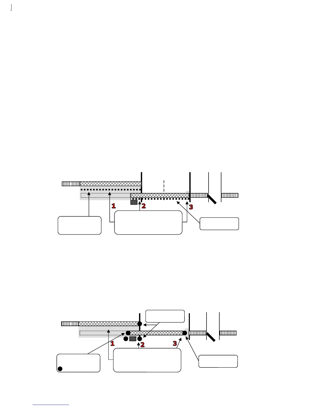
Protect against all entrapments areas that exist:
1. Between the gate and the adjacent fence when the
gate is in the open cycle
2. The gate operator and the slide gate when the gate
is in the open and close cycles
3. At the front end of the gate when the gate is in the
close cycle.
Open beams help protect areas
between the gate and the adjacent
fence. CAUTION: This beam
should be used in conjunction with
a contact sensor.
Close beams help prevent the
gate from hitting obstructions
during the close cycle.
Pedestrian
Access
Fence
Fence Fence
Protect against all entrapments areas that exist:
1. Between the gate and the adjacent fence when the
gate is in the open cycle
2. The gate operator and the slide gate when the gate
is in the open and close cycles
3. At the front end of the gate when the gate is in the
close cycle.
Trailing edge sensor helps protect
areas between the gate and the
adjacent fence.
= Edge Sensor
Leading edge sensor helps
protect areas in front of the
gate.
Post edge sensors help protect
areas inside and outside of the
gate and around the operator