332P950 Rev2
(3325 Service Manual)
Page 2 of 4
G
E
F
D
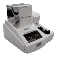
5. Return the instrument to its upright posi-
tion and carefully rotate the rear of the
cover up and away from the bottom cover
while keeping the front portion close to
the bottom cover (D).
6. Unplug the keypad cable (E) and the dis-
play cable (F) from the connectors on the
circuit board assembly, and remove the
instrument cover.
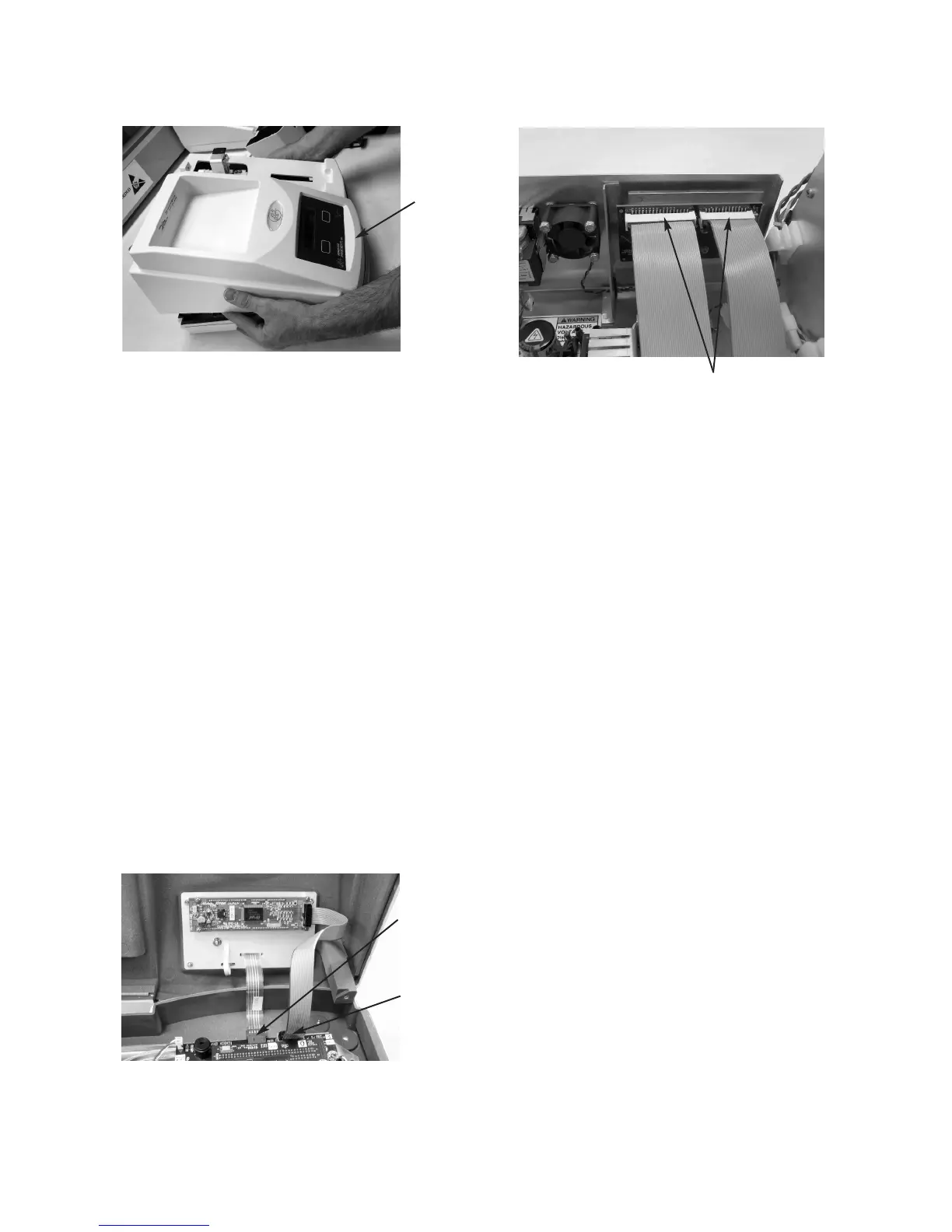
7. Disconnect the two ribbon cables (G)
from the connectors on the rear panel cir-
cuit board.
8. Using the photos in Figures 1, 2, and 3
and your instrument serial number, deter-
mine if you have a suffix A (Figure 1) or
suffix B (Figure 2) power supply. You
may also have a suffix A power supply
that has been previously upgraded to the
suffix B version (Figure 3).
If you have the suffix A power supply
(Figure 1) and have ordered kit 332950R:
You should have received a new suffix B
power supply, DC replacement harness, AC
replacement ground wire, and a mounting
plate with hardware. Continue steps 9 - 16:
9. Remove your old power supply input
cable (I).
10. Remove and discard the ground wire (H)
and DC output cable (K), but keep any
mounting hardware. (Cable replacements
are included in the 332950R kit.)
11. Remove the four mounting screws (J).
12. Locate the new ground wire (H) and
install it on the chassis stud using the
original hardware.
13. As shown in Figure 3, install the mount-
ing plate (L) using the original power
supply mounting screws (J).
14. Install the new power supply on the
mounting plate using included hardware
(M). Note the installation of the replace-
ment ground wire under one of these
mounting screws (see Figure 3).