J
I
J
K
H
332P950 Rev2
(3325 Service Manual)
Page 3 of 4
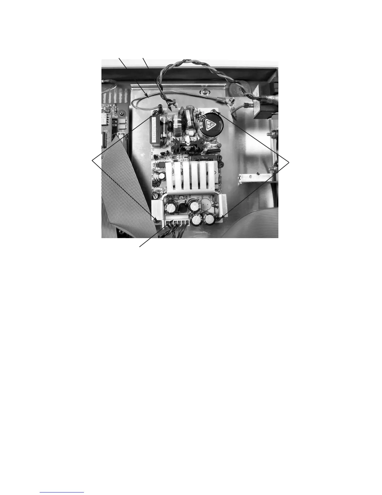
15. Locate the new DC output harness (K).
Install it on the output connecter and then
install the remaining connections to the
Application PCB and the rear panel cool-
ing fan (Figure 3).
16. Reassemble the instrument by reversing
steps 1 - 7, noting the proper pin 1 orien-
tations for all cable assemblies and their
connectors
If you have the suffix B power supply
(Figure 2), or a suffix A instrument that
was previously upgraded to suffix B power
supply (Figure 3): You should have
received parts kit 332951R. Continue steps
17 - 21:
17. Remove and replace the power supply
only by removing input (I) and output (K)
wiring connectors.
18. Remove the four mounting screws (M)
and the ground wire (H).
19. Replace the power supply using the same
hardware and ground wire (H).
20. Reconnect the input (I) and output (K)
connections.
21. Reassemble the instrument by reversing
steps 1 - 7, noting the proper pin 1 orien-
tations for all cable assemblies and their
connectors.
Figure 1. Suffix A Power Supply