2.3.2 Removing a Loop Driver Card
To remove a loop driver, remove all power and follow the procedure above but:
Take a firm hold of top of the loop driver card. Gradually and carefully pull the loop driver vertically
away from the base card and guide it out of the slots in the card guides.
2.4 Plug-In / Peripheral Bus Modules
All panels provide provision for installation / use of local peripheral cards to provide additional functions. The
peripherals are connected via an isolated bus interface.
Each panel supports either a plug-in 2-Way Relay card or a plug-in General Routing Interface card (peripheral
bus module).
All panels also support the connection of up to sixteen Mxp-034 4-Way Programmable Sounder Modules
, up
to sixteen Mxp-035 4-Way Programmable Relay Modules and other peripheral bus modules housed in separate
enclosures. All panels except the small enclosure (/S) support the mounting of one peripheral module on the
chassis plate.
Refer to the wiring installation section (2.5.8) for details of how to connect the peripheral modules and section
(2.5.5) for details of the network connections.
2.4.1 Routing Interface Card (Plug-In)
Outputs to Routing Equipment – Clauses 7.9 and 8.9.
Output to Fire Protection Equipment – Clause 7.10
The Routing Interface Card provides monitored outputs for connection to
Fire Routing Equipment (Item E) and Fault Routing Equipment (Item J)
or to Fire Protection Equipment (Item G) in accordance with EN54-2.
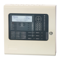
The Mxp-532 Interface
card is fitted to the
base card using 1x M3
screw and 3x plastic
pillars. A metal pillar is
pre-fitted to the base
card. Refer to the
diagram opposite.
All signals and power
required for operation
of the card are
provided on the plug-in
connections.
Ensure that the
connections are
correctly aligned.
The screw fixing is
essential for EMC
Immunity protection.
No Serviceable Parts Inside
Mounting Position for the Routing Interface Card
Isolate ALL sources of power before installing or removing printed circuit boards.
Observe anti-static precautions at all times when handling printed circuit boards.
The Mxp-034 and Mxp-035 modules must be configured using the PC CONFIG TOOL. A maximum of 32 modules (of any type) can be connected only. Refer
to the installation guides provided with each module for further details.