2.4.5 VdS Interface Module Chassis Mounting
An Mxp-504 VdS Interface Module can be installed onto the chassis plate in the medium, large and deep
enclosures.
Outputs to Routing Equipment – Clauses 7.9 and 8.9.
The Routing Interface Card provides monitored outputs for connection to
Fire Routing Equipment (Item E) in accordance with EN54-2.
This card also provides a serial interface and power to FAT and FBF devices and an interface to
an FSD key deposit box adaptor.
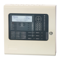
The circuit card is fitted to the chassis using 4x M3 screws.
The screw fixing is essential for EMC Immunity protection.
All signals and power required for operation of the card are provided on the ribbon cable
connections.
No Serviceable Parts Inside
Mounting Position on Chassis.
Isolate ALL sources of power before installing or removing printed circuit boards.
2.4.5.1 Option Relay Card
An optional Mxp-508 (8-Way Relay Card) can be mounted on top of the interface card to provide
additional relay output circuits. Use the supplied pillars to secure the Interface card to the chassis
using the lower 4 mounting holes. Mount the relay card onto the pillars using the supplied M3
screws and connect the ribbon cable between PL1 on the relay card and PL3 on the interface
card.
2.4.5.2 Optional Redundant Ring Controller
An IFAM ADP-N3E Redundant Controller (Master) or ADP-N3S (Slave) can be installed alongside
the VdS Interface card to provide a redundant ring transmission path to FAT and FBF devices.
In the /D enclosure, this circuit card can be fitted to the enclosure sidewall using 4x M3 screws.
For other enclosure sizes, the card must be mounted in a separate enclosure that is connected to
the panel via rigid conduit and must be located ≤ 3 metres from the panel.
See Section 2.5.13.2 for wiring connection information.