2.4.4 Peripheral Module Chassis Mounting
A Peripheral Module can be installed onto the chassis plate in the medium, large and deep enclosures.
The peripheral card is fitted to the chassis using 4x M3 screws.
All cards require connections to a 24V DC supply (AUX 24V) and to the PBUS communications.
Refer to wiring section for further information.
The screw fixing is essential for EMC Immunity protection.
No Serviceable Parts Inside
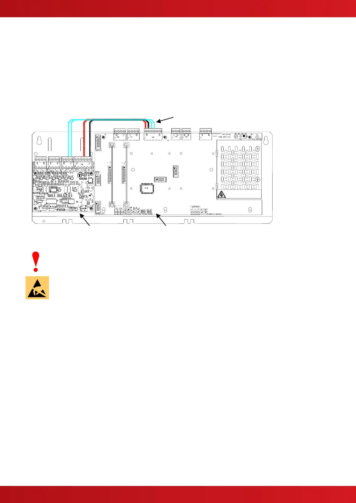
Power and Data
Route along edge of chassis and tie
in place with tie-wraps.
Mounting Position on Chassis – MXP-034 4-Way Sounder shown.
Isolate ALL sources of power before installing or removing printed circuit boards.
Observe anti-static precautions at all times when handling printed circuit boards.