The Plug-In Routing Interface is used to
output monitored signals to Fire Routing
Equipment and Fault Routing Equipment
or to Fire Protection Equipment.
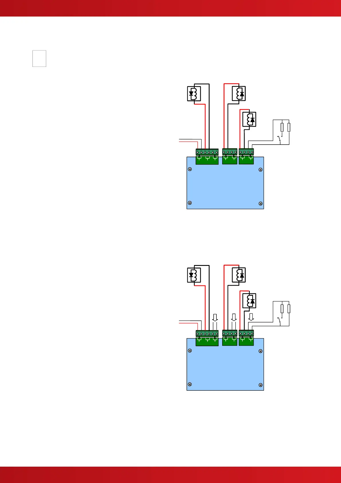
2.5.12.1 Fire / Fault Routing
Each function comprises of an output circuit and
an input (confirmatory) circuit.
Each output is monitored for open circuit and short
circuit wiring conditions in both the activated and
quiescent states and can be connected to a
remote relay coil with a resistance of 1KΩ to 5KΩ.
A suppression diode must be connected across
the coil – observe connection polarities.
If an output is not used install a 4700Ω ½W
resistor across its output terminals.
The Fault Output is normally energised during the
quiescent condition – it will de-energise on any
fault or on total loss of power.
Each associated input circuit is monitored for open
circuit and short circuit conditions using and EOL
resistor (10KΩ).
The primary Fire Routing Circuit is automatically
switched to a failsafe input should the panel suffer
a system fault or total power failure. If required,
this input should be connected to and driven by
another fire routing output located on a separate
panel.
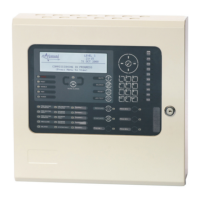
2.5.12.2 Fire Protection Routing
The Interface monitors the wiring to and from the
Fire Protection function (i.e. Extinguishing panel).
A separate circuit card (MXP-506) is available to
mount in the fire protection equipment to provide
the required end of line relays for the output
signals and end of line resistors for the return
signals.
Typical functions are shown in the diagram
opposite. The outputs are fully configurable in the
software.
It is possible, for example, to provide two separate
output release circuits where the fire protection
equipment requires more than one physical
activation signal.