8
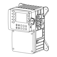
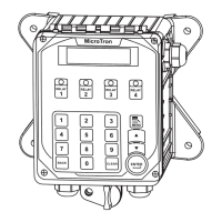
Mounting Instructions
Select a mounting location that provides the operator easy access to the unit and a clear view of the
controls through the cover of the controller. The location should be convenient to grounded electrical
connections, the needed sample line plumbing, and should be on a stable vertical surface.
Electrode Installation
A. Cooling Tower
compensated for increased accuracy.
NOTES:
1. Install an isolation valve on either side of the ow assembly so electrodes can be
easily isolated for removal and cleaning.
2. A line strainer is recommended upstream from the probes to protect against fouling
and damage.
3. Mount pH or ORP electrodes vertically.
4. Green solution reference wire must be connected to either pH or ORP sensor. If both
pH & ORP are present on system card, only one solution reference connection is
needed.
5. Systems with a ow switch require 2-3 gpm ow rate to operate outputs.
WARNINGS:
1. Electrodes are O-ring sealed, which if damaged will cause a leak.
2. Do not allow pH sensor tips to dry out, damage will occur.
3. Do not exceed a water temperature range of 32°F to 140°F.
4. Do not exceed a maximum pressure of 125 psi.