Utility Software
A-
10
ADAM 4100 Series User’s Manual
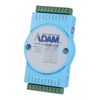
The input signal of Channel 1
2.1 The condition of channel 1 is input range +/- 1V and filter 20%
2.2 20% of FSR(full scale range) means 0.4V
2.3 The time interval T1~T2 equals to sampling time
2.4 Conclusion is the difference between V1@ T1 and V2@T2 is
0.7-0.2 =0.5V > 0.4V, so signal V2 will be ignored
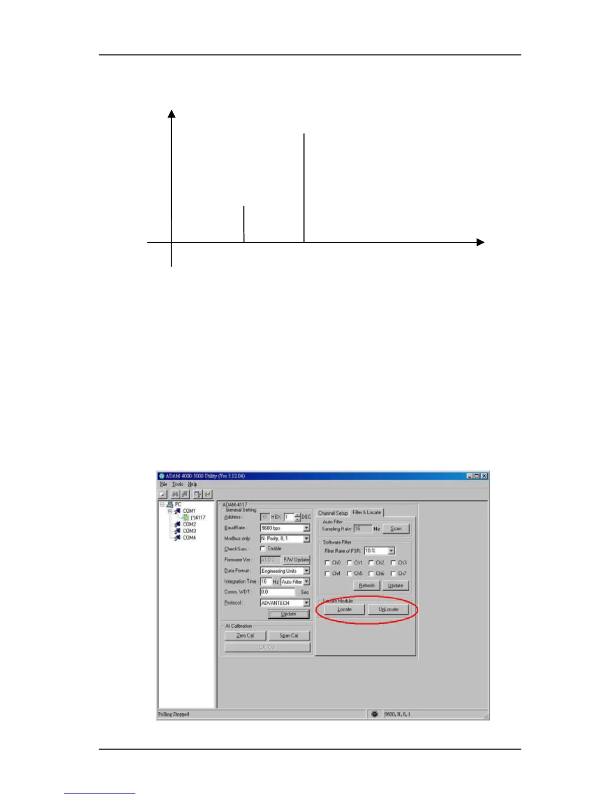
If you want to locate specific ADAM-4100 series, the configuration utility
provides a “Locate” function to assist you. When you select a specific device,
the LED that represents “Status” will be flashing for 8 minutes. If the
“Locate” button is clicked, the “Status” LED will stay on.
Figure A-11 Located mode Function
T1 T2 Time
V(input signal)
V1=0.2
V2=0.7