4-42 ADAM-5510/P31
I/O Modules
C0A+
COA-
COB+/D+
C1A+
C1A-
C1B+/D+
C1B-/D-
C2A+
C2A-
C2B+/D+
C2B-/D-
C3A+
C3A-
C3B+/D+
C3B-/D-
COB-/D-
GND
GND
GND
GND
GND
GND
GND
GND
ISOLATE
TTL
ADAM-5080
4 C/F
V
0
Internal Logic
Vcc
selected, it means the Alarm status will be "latched" whenever the
alarm being triggered. Once the alarm status being "latched," it will
thereafter stay in that triggered state. Users will have to issue a "Clear
Alarm Status" command to return the "latched" alarm status back to
normal. Users can designate the high-limit value and low-limit value to
regulate your alarm behavior through the utility program.
Digital Output Mapping
Users can either run the utility program or issue a "Set Alarm Connet-
ion" command to designate a specific digital output module for the
alarm signal to be sent through.
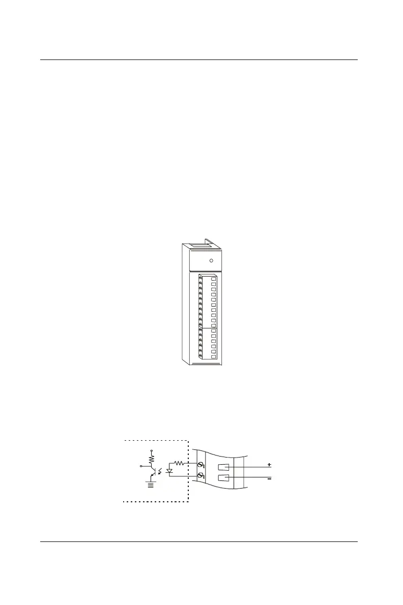
ADAM-5080 Module Diagram
Figure 4-40: ADAM-5080 Module
ADAM-5080 Application Wiring
Figure 4-41: Isolated Input Level
 Loading...