ADAM-5510/P31 2-13
Chapter 2
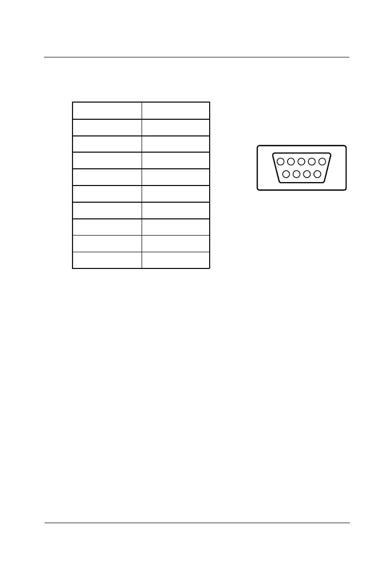
to check the pin assignments for the connector. The following table
shows the pin assignments for the COM1 port.
1
5
9
6
Table 2-3: RS-232 port pin assignments
RS-485 port connection
The COM2 (2F8) port is dedicated as an RS-485 interface. Screw
terminals DATA- and DATA+ are used for making the COM2
RS-485 connections.
2.7 LED Status of the ADAM-5510/P31 Unit
The ADAM-5510/P31 unit front panel cover has four LEDs which
indicate operating statuses. Please refer to Section 1.3.1 for details.
2.8 I/O Modules Configuration
When main unit installation is completed, you may still need to
configure or calibrate the I/O modules inserted in the ADAM-5510/P31
slots. The utility program ADAM5510.EXE can help you do this. See
Section 0.3.2 I/O modules configuration in Chapter 0. Greater detail is
provided in Chapter 4.
Pin No. Description
Pin 1 DCD
Pin 2 RxD
Pin 3 TxD
Pin 4 DTR
Pin 5 GND
Pin 6 DSR
Pin 7 RTS
Pin 8 CTS
Pin 9 RI
 Loading...