B-2 ADAM-5510/P31
Register Structure
This appendix gives a short description of each of the module’s
registers. For more information please refer to the data book for the
STARTECH 16C550 UART chip.
All registers are one byte in length. Bit 0 is the least significant bit, and
bit 7 is the most significant bit. The address of each register is speci-
fied as an offset from the port base address (BASE). COM1 is 3F8h
and COM2 is 2F8h.
DLAB is the "Divisor Latch Access Bit", bit 7 of BASE+3.
BASE+0 Receiver buffer register when DLAB=0 and the operation is
a read.
BASE+0 Transmitter holding register when DLAB=0 and the
operation is a write.
BASE+0 Divisor latch bits 0 - 7 when DLAB=1
BASE+1 Divisor latch bits 8-15 when DLAB=1.
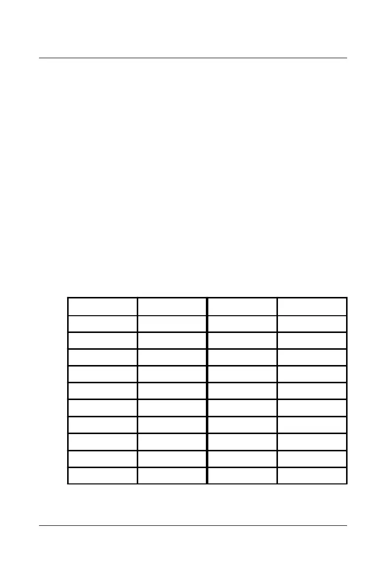
The two bytes BASE+0 and BASE+1 together form a 16-bit number,
the divisor, which determines the baud rate. Set the divisor as follows:
Baud rate Divisor Baud rate Divisor
50 2304 2400 48
75 1536 3600 32
110 1047 4800 24
133.5 857 7200 16
150 768 9600 12
300 384 19200 6
600 192 38400 3
1200 96 56000 2
1800 64 115200 1
2000 58 x x
 Loading...