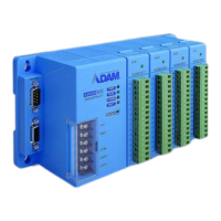
B-4 ADAM-5510/P31
Register Structure
BASE+4 Modem Control Register (MCR)
bit 0: DTR
bit 1: RTS
BASE+5 Line Status Register (LSR)
bit 0: Receiver data ready
bit 1: Overrun error
bit 2: Parity error
bit 3: Framing error
bit 4: Break interrupt
bit 5: Transmitter holding register empty
bit 6: Transmitter shift register empty
bit 7: At least one parity error, framing error or break
indication in the FIFO
BASE+6 Modem Status Register (MSR)
bit 0: Delta CTS
bit 1: Delta DSR
bit 2: Trailing edge ring indicator
bit 3: Delta received line signal detect
bit 4: CTS
bit 5: DSR
bit 6: RI
bit 7: Received line signal detect
BASE+7 Temporary data register

 Loading...