ADAM-5510/P31 E-7
Appendix E
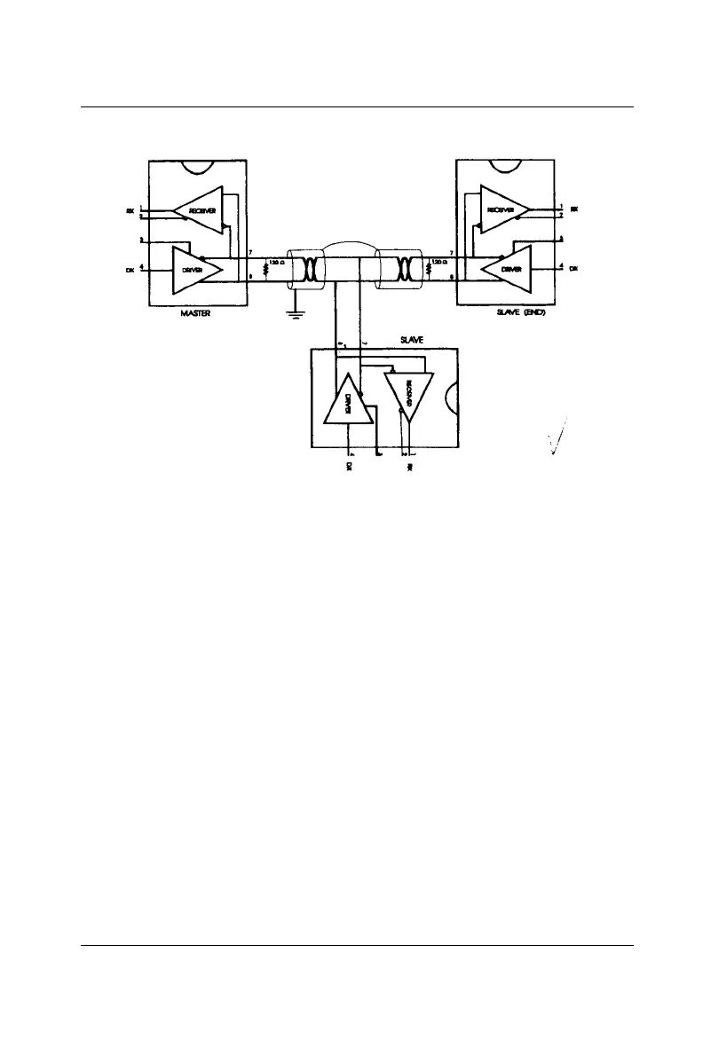
Figure E-5: Termination resistor locations
Because each input is biased to 2.4 V, the nominal common mode
voltage of balanced RS-485 systems, the 18 kΩ on the input can be
taken as being in series across the input of each individual receiver.
If thirty of these receivers are put closely together at the end of the
transmission line, they will tend to react as thirty 36kΩ resistors in
parallel with the termination resistor. The overall effective resistance
will need to be close to the characteristics of the line. The effective
parallel receiver resistance R
P
will therefore be equal to:
R
P
= 36 x 10
3
/30 = 1200 Ω
While the termination receptor R
T
will equal:
R
T
= R
O
/ [1 - R
O
/R
P
]
Thus for a line with a characteristic impedance of 100 Ω resistor
R
T
= 100/[1 - 100/1200] = 110 Ω
Since this value lies within 10% of the line characteristic impedance.
 Loading...