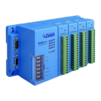
1-4 ADAM-5510/P31
Introduction
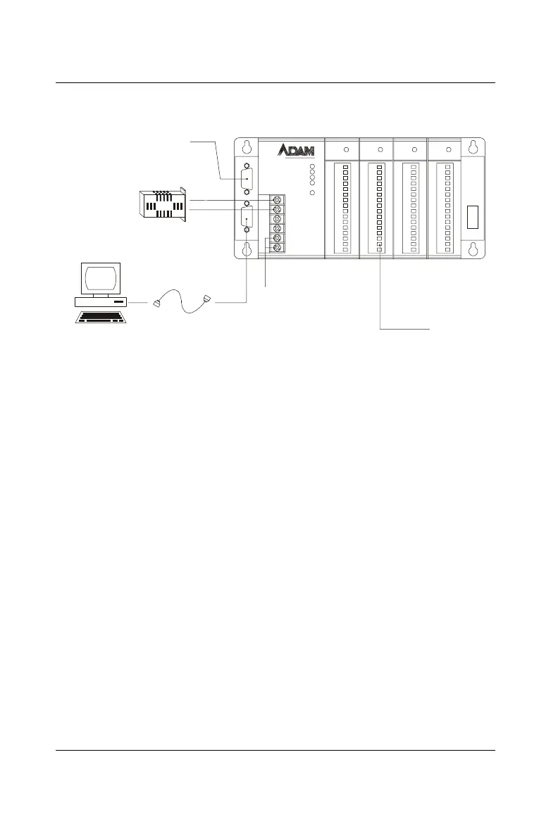
Figure 1-1: ADAM-5510/P31 system configuration
1.3.1 LED Display
There are four LEDs on the ADAM-5510/P31 front panel. The LED's
indicate ADAM-5510/P31's operating status, as explained below:
(1) PWR: power indicator. This LED is on whenever the ADAM-5510/
P31 is powered on.
(2) RUN: program execution indicator. This LED is reqularly blinks
whenever the ADAM-5510/P31 is executing a program.
(3) COMM: communication indicator. This LED blinks whenever the
host PC and the ADAM-5510/P31 are communicating. Please notice: if
the host COM port is connected to the ADAM-5510/P31's RS-232 port,
this LED will normally be off. On the other hand, if the host COM port
is connected to the ADAM-5510/P31's RS-485 port, this LED will
normally be on.
(4) BATT: battery status indicator. This LED will be on whenever the
SRAM backup battery is low.
COMM
PWR
BATT
RUN
RESET
GND
+Vs
COM
DAT A+
DAT A-
ANALOG INPUT
ANALOG OUTPUT
DIGITAL INPUT
DIGITAL OUTPUT
COM2 RS-485
PROGRAMMING
PORT RS-232
DB-9
POWER SUPPLY
+10 - +30 V
DC
COM1 RS-232
HOST COMPUTER
ADAM-5510
P31
ADAM-5510
PA RA D Y M- 3 1
 Loading...